








What a grounding loop is and why it is needed in a private house
A grounding device is a system of metal elements in the soil that diverts leakage current and lightning discharge into the ground. Without it, the body of an appliance becomes energized when the insulation breaks down, and the house will not be signed off for commissioning.
How a grounding loop is structured and what elements it consists of
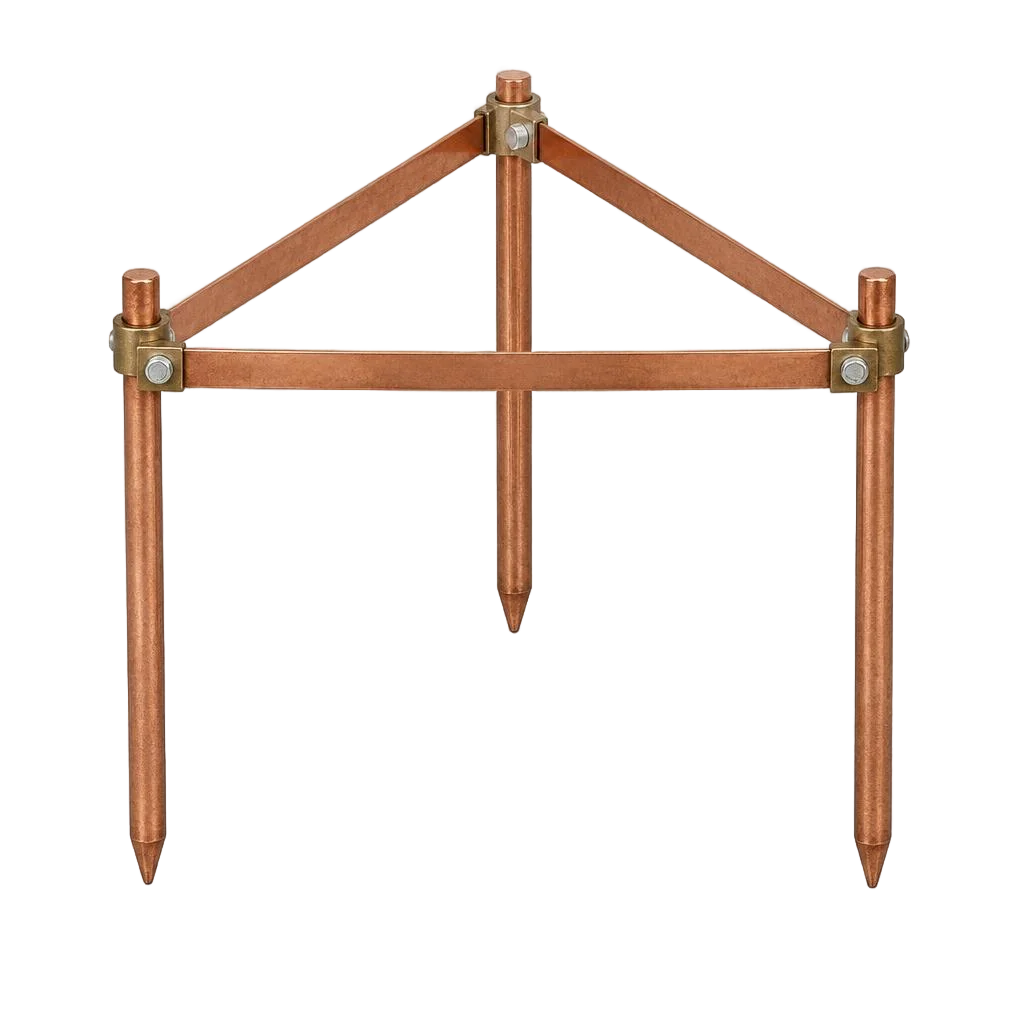
The design of a grounding loop comes down to three connected assemblies: vertical ground electrodes immersed in the soil, a horizontal connecting strip, and a grounding conductor routed to the main grounding busbar (MGB) in the panel. The rods are driven to a depth of 2.5–3 meters in order to reach moist layers that are stable across seasons; they are connected with a 40×4 mm strip by a welded seam along the entire perimeter. From the MGB, individual PE cores run out to socket groups, the boiler, and metal pipes. The immersion depth of the rod matters more than its thickness: resistance drops from contact with the moist soil layer, not from the area of metal, which is why a 14 mm copper-bonded rod at three meters performs better than a 57 mm pipe at one and a half. That is precisely why organizing grounding in a private house begins with the geology of the plot, not with the area of the building — on gravel and sand the scheme is reassembled for the specific soil. In requests, clients often write about installing a loop — and from that wording it is immediately clear that the person needs a calculation for their own plot, not general theory.
Which grounding schemes are used for a 220/380 V house
- TN-C-S: the working scheme for Bishkek — the PEN at the service entrance is split into N and PE, and the PE is re-grounded on the busbar at the panel; suitable if a four-wire line comes from the substation.
- TN-S: five separate cores from the substation to the panel, including an independent PE; rarely found in the private sector, more often in new neighborhoods with cable service entrance.
- TT: a separate grounding loop for the house and a mandatory RCD at the service entrance; used when there is no PE conductor from the network and there is nowhere to take it from.
- Re-grounding at the service entrance: standardized at 10 ohms and protects against a broken neutral on the line — during an accident at the substation, the potential does not go into the bodies of appliances.
- PE busbar in the panel: the point where the conductor from the loop, the re-grounding, and all protective cores of the house converge; at Eco-Service it is marked separately from the working neutral.
What grounding resistance is considered the norm
| Purpose of the loop | Standard | Target resistance |
|---|---|---|
| Electrical installation of a private house | PUE 1.7 | 30 ohms |
| Re-grounding at the service entrance | PUE 1.7 | 10 ohms |
| Gas equipment, boiler | PUE 1.7 | 4 ohms |
| Lightning protection | SO 153-34.21.122-2003 | 4 ohms |
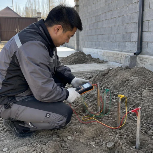
The norm depends on the purpose of the loop, not on the power of the house: the same rod may give 8 ohms for the panel and fail to meet the standard for the boiler. That is why, before handing over a facility, they order the installation of grounding in a private house, and the work is completed with a control measurement using an MRU-200 or IS-20 device — a calculation based on the soil beforehand provides only a guideline, and the fact is confirmed only by measurement. Designers in Kyrgyzstan follow PUE 1.7, and for lightning protection they additionally check against SO 153-34.21.122-2003, where the requirements for impulse resistance are stricter. In requests, wording such as "grounding loop in a private house" also appears — from it we understand that the person needs turnkey installation, not a consultation. Separately, clients ask about the installation of grounding in a private house — and here it is correct to name not a sum, but the scope of work: it depends on the soil, the number of rods, and the length of the route to the panel.
Types of grounding loops: modular, classic, linear
The three types of loop differ in the technology used to drive the electrodes and their suitability for a specific soil. Let's look at which of them provides stable resistance on a plot in Bishkek and its suburbs.
Modular rod grounding: technology and when to choose it
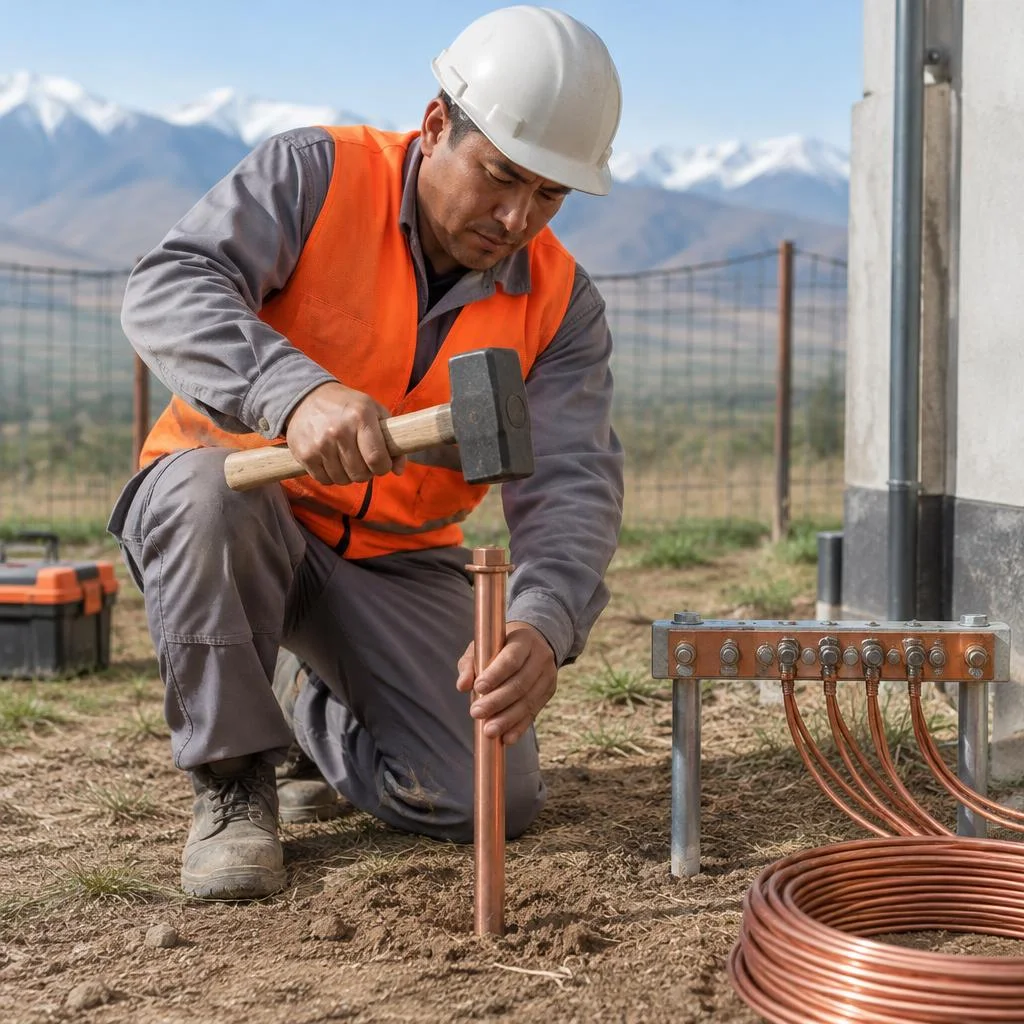
Eco-Service installs modular rod grounding by driving copper-bonded rods of 1.5 m each, extending them with couplings to a design depth of 6-12 m. Each rod is seated on a connecting coupling, a tip with a driving head is placed on top, and a vibratory hammer drives the section into the ground — the sequence "rod → coupling → design depth" is repeated until the instrument shows the required spreading resistance. This scheme wins on the loam of Bishkek and the dry soil of the foothills: the rod pierces dense layers and reaches a consistently moist horizon, where a classic angle stops at 2-2.5 m and does not meet the standard. On rocky plots near Ala-Archa and Kant, driving stops earlier — before starting, we test the soil and allow a margin in the number of sections. Clients often phrase the request as: installation of modular grounding — and from that phrase we immediately understand that the plot has problematic soil. Practice shows: on sites with a shallow rocky sublayer, it is cheaper to calculate a classic loop right away than to buy extra sections blindly.
Classic triangle loop and linear scheme
A classic grounding loop in a private house is assembled from 50×50 mm angle steel driven in a triangle or in a line and welded to 40×4 mm strip. The triangle is placed at the vertices with a side of 2.5-3 m: the three electrodes influence each other and provide better current spreading than a row. The linear scheme — angles in a row with a spacing of 2-3 m — is simpler to mark out and dig a trench for, so it is chosen on a narrow strip between the house and the fence, where a triangle does not fit. Driving goes to 2-2.5 m, below the freezing depth, so that seasonal moisture fluctuations do not lower the parameter. The 40×4 mm strip bonding is welded to each angle, the seam is cleaned and coated with bitumen. In requests, this work is described briefly: installation of a grounding loop — and then we clarify the scheme and the number of electrodes. Separately, clients write installation of grounding in a private house — and from that wording it is clear that the person needs a turnkey loop, not a single electrode. After bonding, we measure the resistance: if it is above the standard, we add a fourth electrode in the gap.
Comparison of loop types by soil, depth and installation complexity
| Loop type | Soil | Immersion depth | Plot area |
|---|---|---|---|
| Modular rod | loam, sandy loam, sand | 6-12 m | from 1 m² |
| Classic triangle | loam, clay | 2-2.5 m | from 3×3 m |
| Linear | loam, clay | 2-2.5 m | strip 6-9 m |
Grounding installation stages: from marking to connection to the panel
The work proceeds strictly in stages — from calculation and marking to measurements. Violating the order leads to redoing the loop and extra costs for digging up a backfilled trench.
Resistance calculation and marking of the ground electrode route
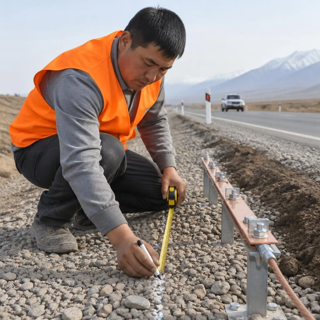
Eco-Service begins with calculating the loop resistance based on soil resistivity and marking the ground electrode route taking into account underground utilities. On clay and loam, the standard is achieved with three rods 3 m long, while on sandy soil near Bishkek it may take five to six rods or a deep ground electrode of 9-12 m. Soil density is checked with a hand penetrometer or data from the site's geological survey is used, and the route is tied to the water utility and gas service network plans. Marking is done before digging: an accidentally punctured water or gas line costs more than the loop itself, and the route must be at least 1 m away from the foundation. If a 0.4 kV power cable runs nearby, the horizontal spacing is at least 0.5 m. Clients often phrase the request as grounding installation in a private house — and any such job begins with this calculation. In search, people often type grounding loop installation price — and land on this stage, where it is determined exactly how many rods and meters of strip will be needed for the site.
Trench preparation and driving vertical ground electrodes
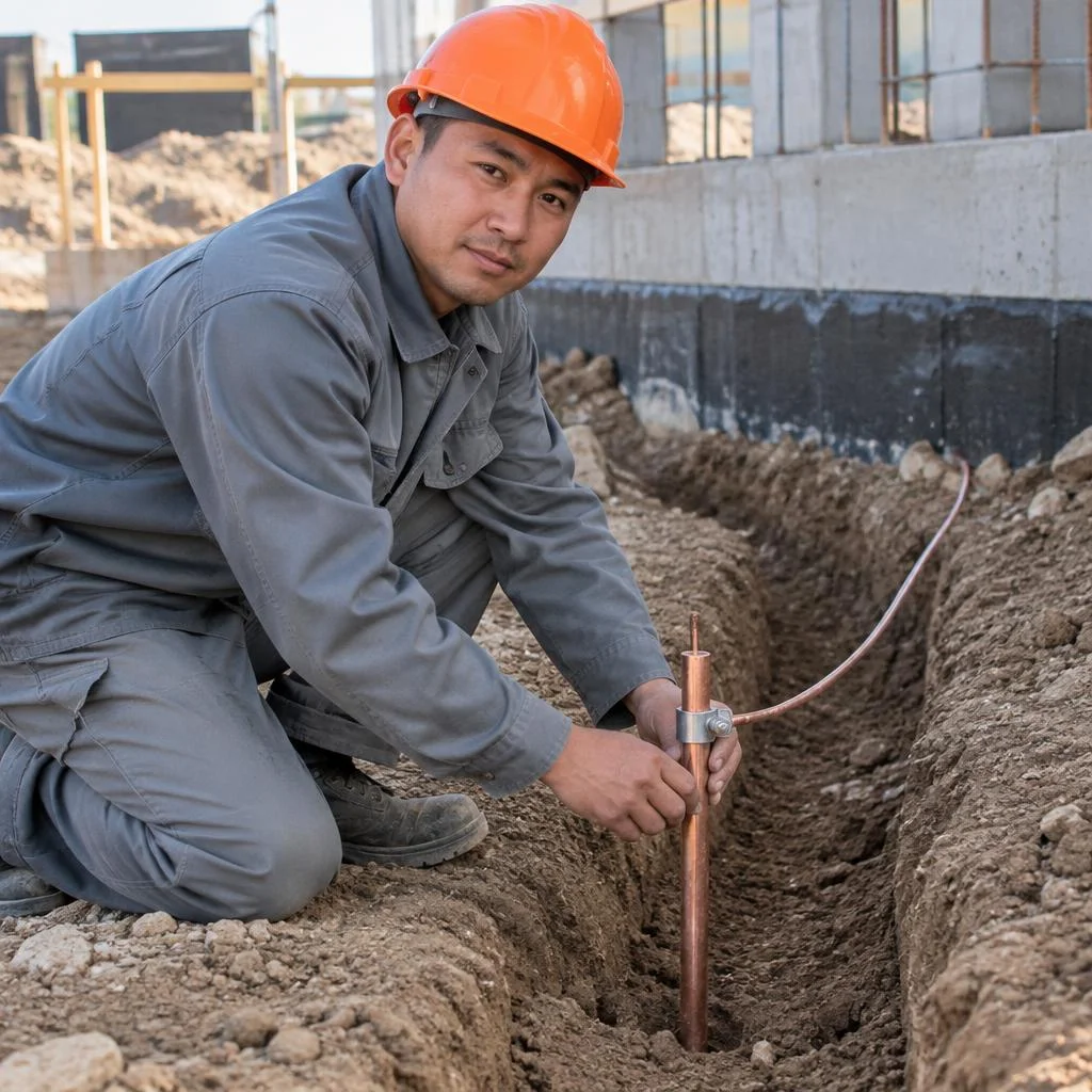
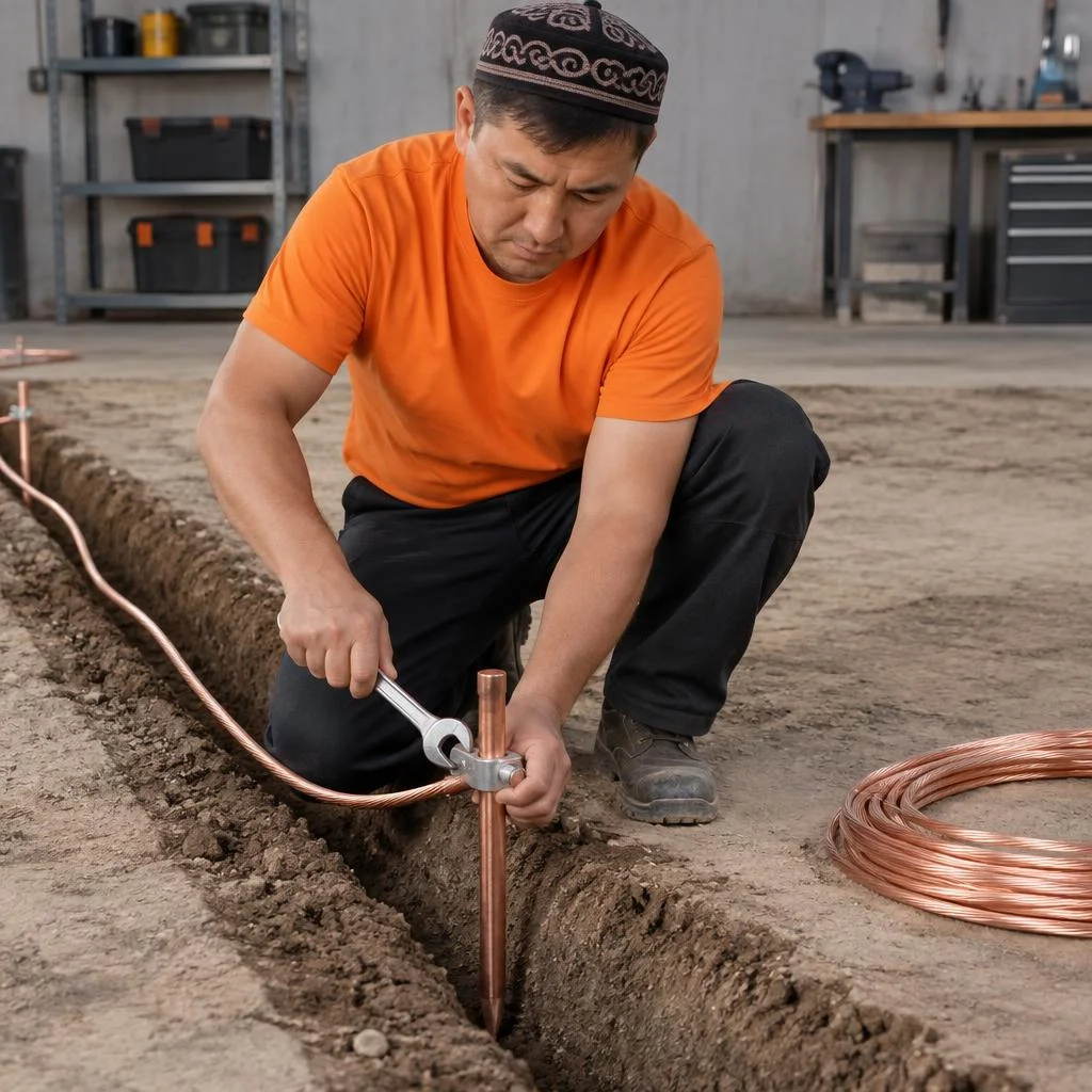
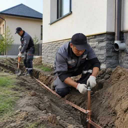
- Trench: dug to a depth of 0.5-0.7 m along the marked route, width — one shovel, the bottom is leveled for laying the bonding strip.
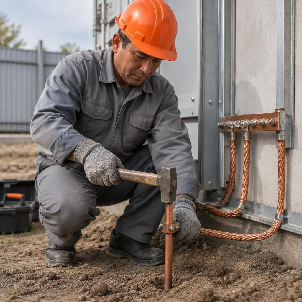
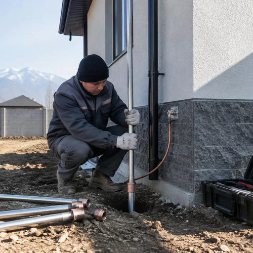
- Driving the electrodes: vertical rods are driven to the design depth with a vibratory hammer or a sledgehammer through a guide, keeping an eye on verticality.
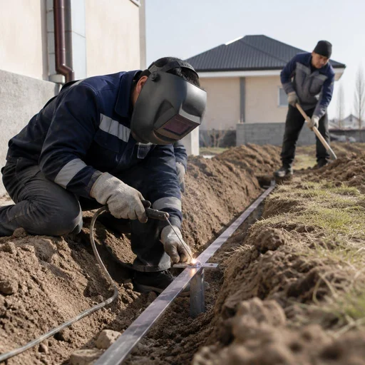
- Bonding the rods: the electrodes are connected with a 40×4 mm strip laid in the trench, with an overlap of at least 100 mm for welding.
- Open loop: the trench is not backfilled until welding and measurements are done — access is left for adding a rod.
- Depth control: driving deeper than the design on sandy soil hurts the rod's grip with the soil, so the depth is checked against the mark on the shaft.
Welding connections and laying the grounding conductor
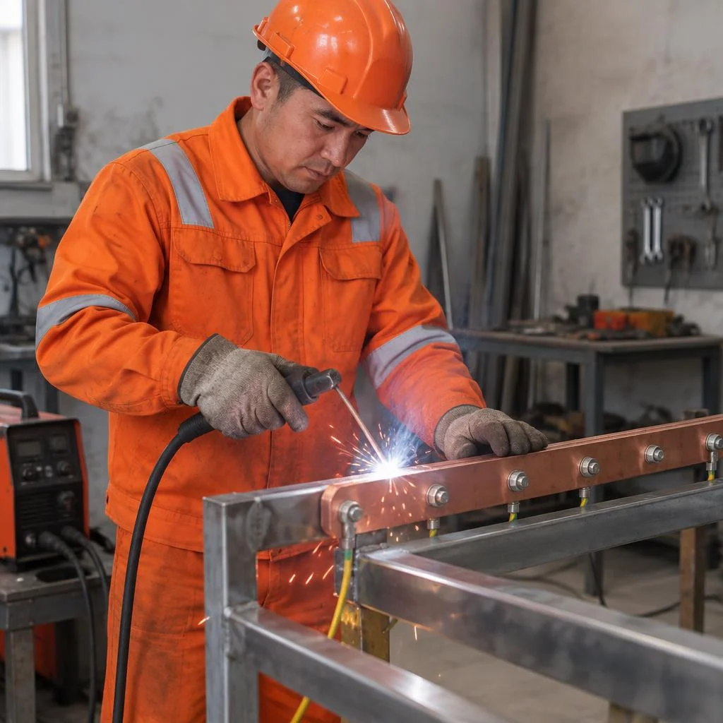
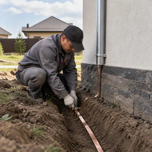
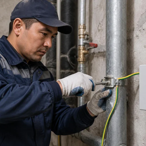
Eco-Service performs the loop connections by welding, and lays the grounding conductor from the loop to the main grounding busbar in the panel. The welds are cleaned of slag, welded on both sides of the overlap and coated with bitumen varnish at the point where they exit the soil — this protects the metal from corrosion for 10-15 years. The conductor up to the entry into the house is run as a strip or copper cable with a cross-section of at least 10 mm² for copper and 16 mm² for aluminum, and is laid in corrugated conduit where it crosses the foundation. An inspection point is brought out 200-300 mm above ground level — a bolted connection is left in it for periodic resistance measurement. Bolted connections in the ground oxidize within 2-3 seasons and lose contact — welding in the ground is more reliable, and a bolt is left only in the inspection point above ground level. It is at this stage that customers clarify the installation of the grounding strip — the 40×4 mm strip is laid in the trench and welded to the rods with an overlap of at least 100 mm. In search, many write briefly: Grounding installation — and the technician immediately understands that this refers to the welding stage, where the strip is connected to the rods.
Connection to the main busbar and grounding of the electrical panel
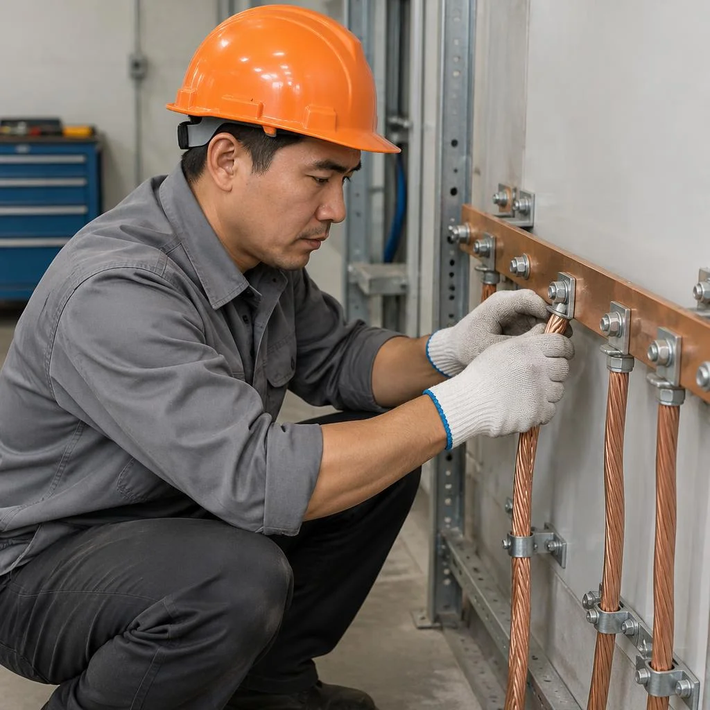
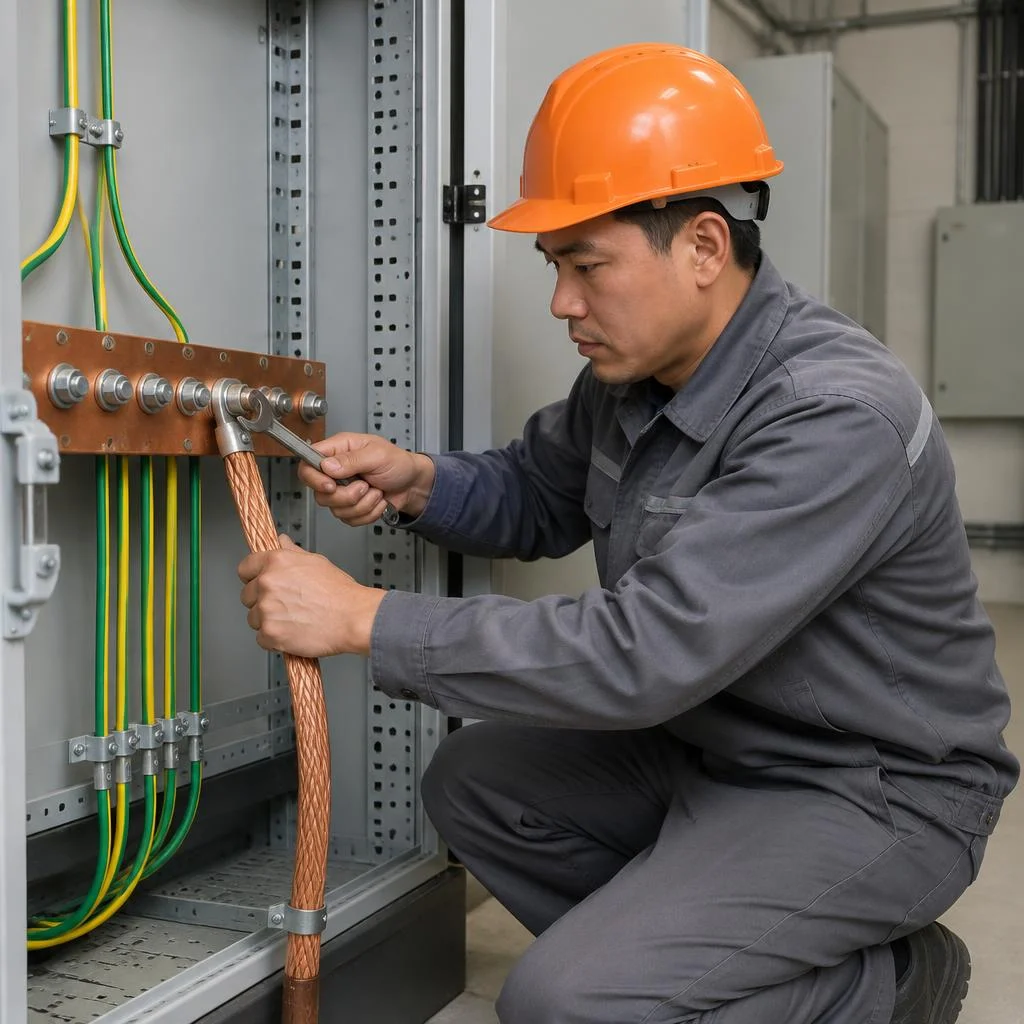
- Connection to the MGB: the grounding conductor is brought to the main grounding busbar in the input panel and secured with a bolt and spring washer.
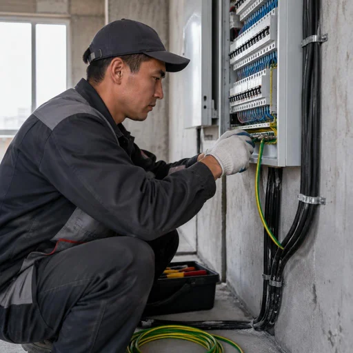
- Grounding the electrical panel: the panel enclosure is connected to the MGB with a separate conductor, and the PE busbar is distributed across the socket and lighting circuits.
- Separation point: the PEN conductor is split into N and PE once — before this point or in the MGB itself; recombining them afterward is not permitted.
- Verification: after connection, the loop resistance and insulation resistance are measured, and the results are recorded in a protocol.
- Handover of work: the external grounding loop and internal wiring are closed out with a single act, and the installation of the external grounding loop is considered complete only after a signed measurement protocol.
Internal grounding: sockets, appliances, boiler, bathtub, pipes
The outdoor ground loop alone does not protect: without internal wiring of the PE conductor and equipotential bonding, the enclosures of appliances remain under dangerous voltage. Let's break down which points in the house are connected to the indoor grounding loop and why each of them matters.
Grounding of the socket group and household appliances
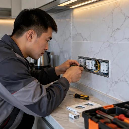
Eco-Service grounds the socket group with a separate PE conductor and connects household appliances to it — a washing machine, refrigerator, microwave oven. The conductor runs from the main grounding busbar as the third core in a VVGng-LS 3×2.5 mm² cable to each socket with a grounding contact, and from there — to the metal enclosure of the appliance via the PE terminal. Such protection closes the chain PE conductor → socket → appliance enclosure: if the insulation breaks down, the current flows to ground, and the circuit breaker trips within fractions of a second. In our practice, the most common occurrence is connection via a "neutral in the socket" — this is dangerous: if the neutral burns out at the substation, the enclosure of the washing machine will be under a phase voltage of 220 V, and a person will touch it with wet hands.
Grounding of the heating boiler and metal bathtub
- Heating boiler: Eco-Service runs a separate conductor from the enclosure of a gas or electric boiler to the equipotential bonding cabinet, without connecting it to the working neutral.
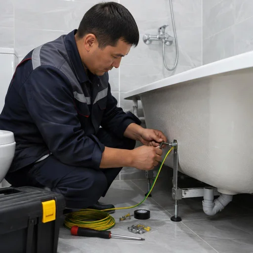
- Metal bathtub: the bowl is connected to the equipotential bonding system with a 6 mm² copper conductor via a bolted connection on the rim or leg.
- Adjacent metal parts: a heated towel rail, chrome faucet, and drain grate are combined into a single unit so that no potential difference arises between them.
- Separate calculation: for a gas boiler the standard is stricter — 4 ohms, so the ground loop for the boiler is calculated separately, and not "by eye" based on the overall resistance of the house.
Grounding of metal pipes and the equipotential bonding system
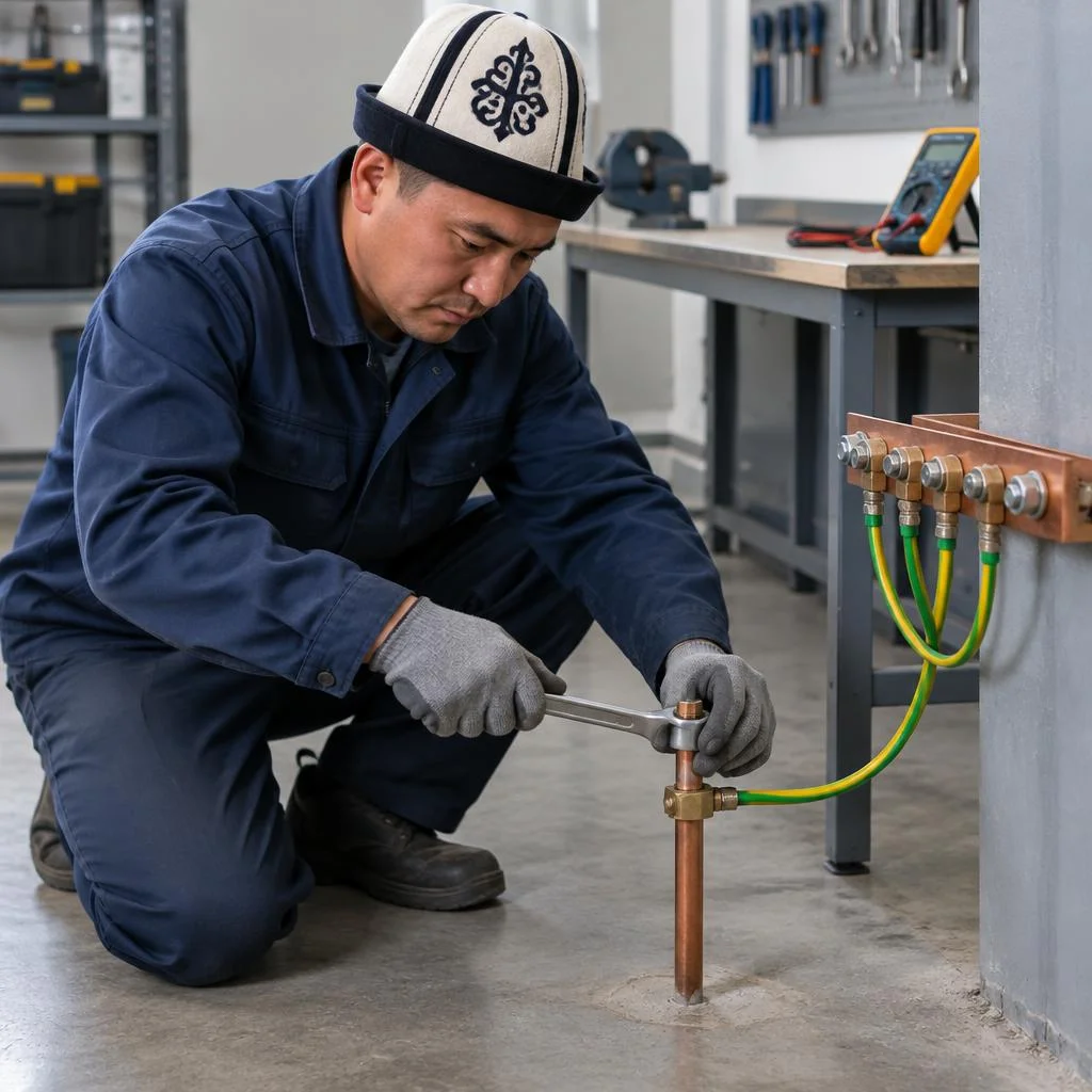
Eco-Service includes metal water supply and heating pipes in the equipotential bonding system via the ShDUP cabinet and the main grounding busbar. The scheme is simple: pipe → ShDUP → GZSh, where each input is secured with a clamp with a spring washer, and the cross-section of the jumper is selected according to the PUE — at least 6 mm² for copper. Installing grounding on plastic pipes is not required: the dielectric does not conduct current, but metal sections after the meter or filter are still grounded. Clients often phrase the request as an indoor grounding loop — essentially it is the same unit that links pipes, appliance enclosures, and the busbar into a single network. People often type "grounding loop for a house" into the search bar — and land on this same unit, just named differently. Equipotential bonding protects not against current in the pipe, but against the potential difference between the pipe and the appliance enclosure — it is precisely this difference that gives an electric shock in the bathroom when a person holds the faucet with one hand and touches the washing machine with the other.
Lightning protection and grounding: lightning rod, down conductor, common loop
Lightning protection does not work without a ground electrode: the discharge must be diverted into the soil, and this is done through the same loop. We explain how the system is structured and whether it can be combined with the house grounding.
How lightning protection of a private house is structured
- Lightning rod: a rod, mesh or cable on the roof that receives the discharge first and prevents it from going into the rafters.
- Down conductor: a conductor from the receiver down along the facade, laid along the shortest path without sharp bends.
- Ground electrode: a loop in the ground where the discharge goes; when installing grounding devices, its resistance is checked separately from the household one.
- Standard: SO 153-34.21.122-2003 sets the protection zones, the spacing of down conductors and the minimum cross-sections of conductors.
- Fasteners: holders are installed at a spacing of 1-1.5 m, on the roof and facade — on a non-combustible base.
- Gap: the down conductor is not fastened tightly to plastic siding — during a discharge the metal heats up, so a gap is left.
Can lightning protection and the house grounding loop be combined
Lightning protection and the house grounding loop can be combined into a single ground electrode if its resistance does not exceed 10 Ohms. In practice, this is the most common option for the private sector of Bishkek: a separate ground electrode for lightning protection requires a second trench, additional rods and welding, while the common loop is already laid under the electrical panel. A lightning discharge is many times more powerful than household leakage current, so combining saves metal but requires a reinforced loop — a weak ground electrode will simply burn out, and the house will be left without protection. The request for a grounding loop for a private house is discussed at consultations most often: owners want to understand whether one trench is enough for both loops. In the search bar, clients often type about the grounding loop — and land on this page, where the difference between a common and a separate ground electrode is explained. The installation of a grounding strip, price per meter, is calculated separately — when combining, the strip is taken with a cross-section of 40×4 mm and laid to a depth of 0.5-0.7 m. Installation of grounding devices is asked about in almost every second inquiry: measuring resistance with an MRU-200 device will show whether the existing rods are enough or new ones need to be added. People also type "installation of grounding devices" into the search bar — this is how those who are looking for a contractor for the entire scope of work at once, rather than a separate service, formulate their request.
Measurements, Protocol and a 2-Year Warranty on the Grounding Loop
A installed grounding loop cannot be considered complete until it has been tested with instruments and documented in a protocol. We explain how measurements are taken, what the document records, and what period the warranty covers.
Measuring Grounding and Insulation Resistance
- Measuring instrument: Eco-Service works with the MRU-200 and IS-20 — they provide results using the voltage drop method with accuracy down to hundredths of an ohm.
- Measurement points: resistance is checked on the main busbar, on each vertical ground electrode, and on remote socket groups.
- Insulation resistance: a separate measurement between the phase and the PE conductor shows whether there is any leakage through damaged cable insulation.
- Recording: the result of each measurement is entered into the protocol, indicating the point, value, and weather conditions at the time of testing.
- Seasonality: resistance must be measured during the dry season — in summer the soil dries out, and a loop that passed in winter may fall short of the norm in July.
What the Protocol Includes and Why It Is Needed
The resistance measurement protocol contains the grounding loop diagram, point-by-point measurements, and a conclusion on compliance with PUE 1.7. The document specifies the soil type, the depth of the ground electrodes, the conductor cross-section, and the results for each measurement — this set is sufficient for the grid organization's engineer to confirm the loop's operability without a repeat visit. The protocol is drawn up after installation and after each control measurement, and is stored together with the completed works certificate and the ground electrode datasheet. The document is needed when connecting a house to the grid, when commissioning a facility, and upon sale — the buyer requests it first thing, because without the document it is impossible to tell that grounding has actually been installed rather than marked by a single rod. In search, clients type "installation of protective grounding" — and land on this page, although what is discussed here is a different stage: the protocol records work already performed rather than describing the process itself. Installation of grounding, the price of which includes measurements and preparation of the protocol, costs less than a separate visit by a measurement laboratory a year later. In search, clients often type "grounding busbar installation price" — and land on this page, although what is meant is a different node: the busbar connects the ground electrodes inside the loop and does not run to the panel.
2-Year Warranty and Frequency of Loop Inspection
- 2-year warranty: covers the installation work and welded connections of the loop — if a failure occurs through the contractor's fault, the visit and rework are at the service's expense.
- Inspection point: inspect it annually — an open terminal above ground will show corrosion before resistance drops.
- Repeat measurement: check resistance with an instrument once every 3 years, and unscheduled after wiring repairs or panel replacement.
- Seasonal control: if excavation work has been carried out nearby, take a control measurement immediately — a displaced ground electrode changes the current dissipation pattern.
- Cost of grounding in a private house: allow a depth margin at the design stage — then repeat measurements stay within the norm even in the dry season.
- Grounding in a private house price: is specified after calculating resistance for the specific soil — a depth margin reduces the risk of redoing the loop.
- Grounding loop price: is formed from the number of ground electrodes and the length of the route, and grounding installation, the price of which includes the protocol, pays for itself by avoiding repeat laboratory visits.
Conclusion
Grounding in Bishkek is work where the soil, the layout, and the measurability of the result are what matter, not the area of the house. We have gathered the key points worth keeping in mind before starting work on a site.
Main takeaways
- Selection based on soil: the ground loop is calculated based on the soil's resistivity and the required current dissipation value, not on the square footage of the building.
- Layout suited to conditions: modular rod grounding wins on loam and dense layers, while the classic triangle wins on stable soil with plenty of space.
- Connections in the ground: welding is more reliable than bolted clamps, and inspection hatches are left only above the surface for periodic inspection.
- Internal part: routing of the PE conductor and equipotential bonding are mandatory — the external ground loop without them does not protect people and equipment.
- Closing out the work: the result is confirmed by a resistance measurement report, not by the fact that metal was buried in a trench.