








What types of cable trays exist and where each is used
The type of tray is chosen according to the nature of the line: power, low-voltage, outdoor, or aggressive environment. We break down six main types and their purpose at industrial, commercial, and infrastructure facilities in Bishkek.
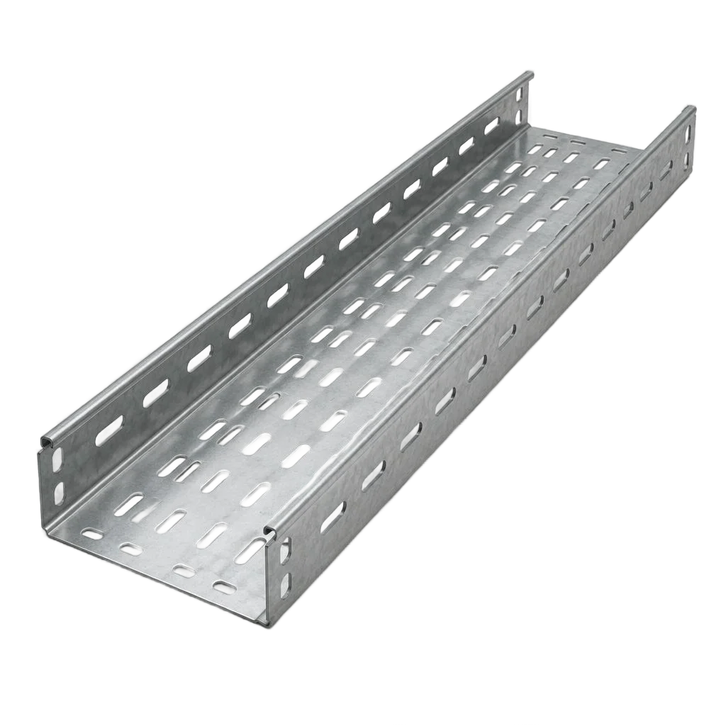
Metal and perforated tray: for power routes
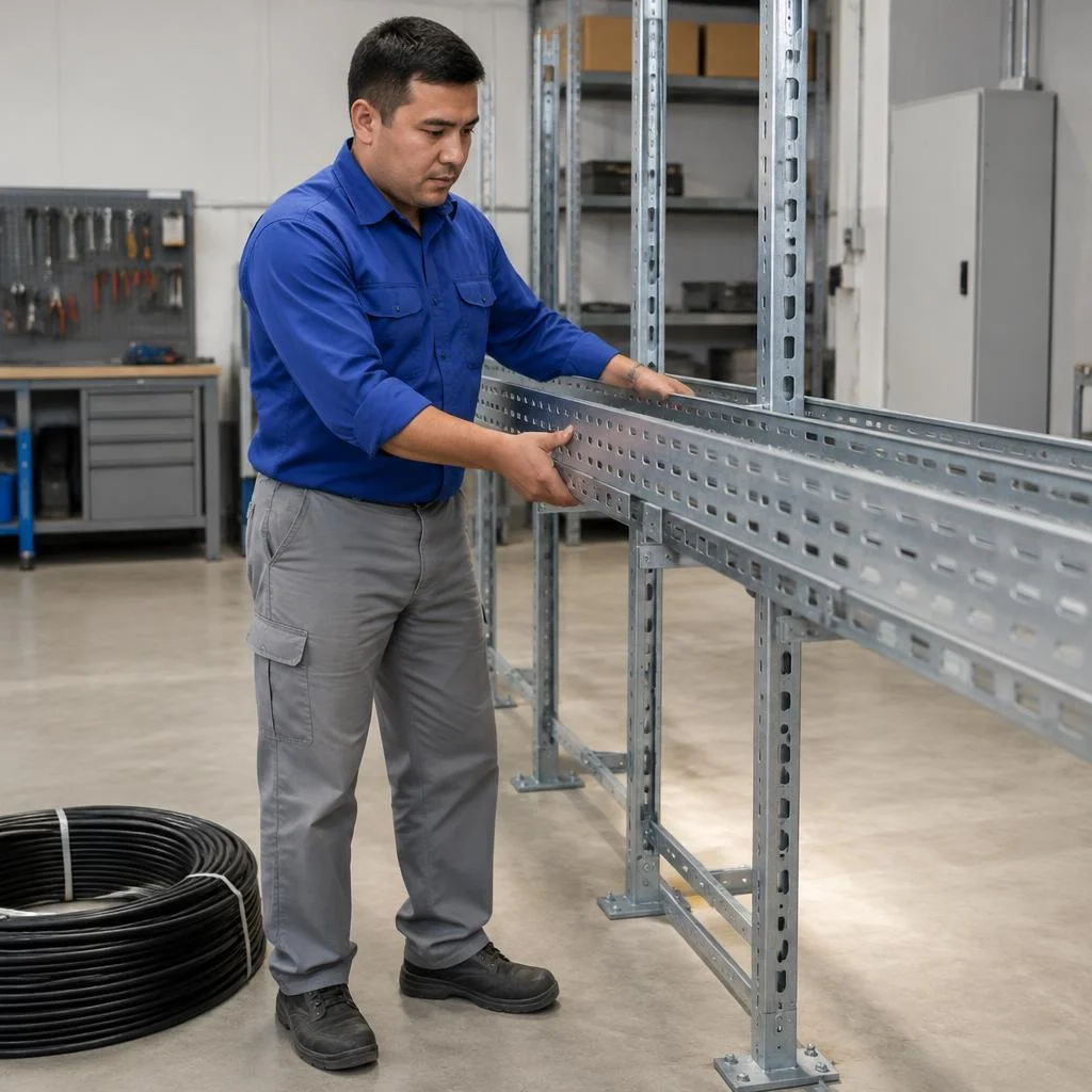
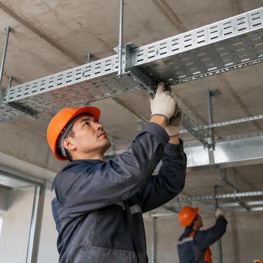
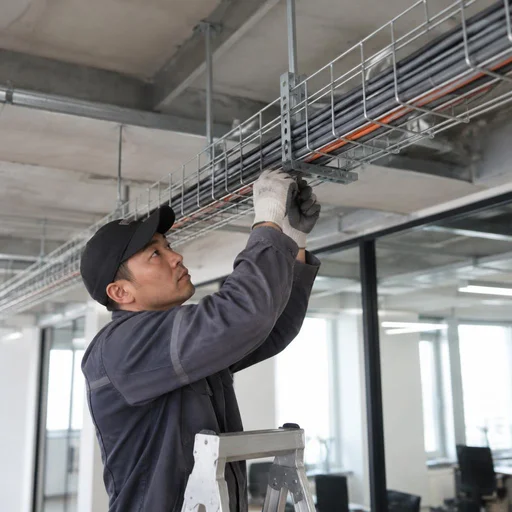
We install metal and perforated trays for power lines at industrial and commercial facilities — perforation provides ventilation and reduces cable heating during dense laying. On routes with a cross-section from 4×95 mm², the perforated version keeps the operating temperature of the conductors 8-12 °C lower than a solid box of the same size, while the tray fill does not exceed 40-50% of the internal volume. Industrial workshops, boiler rooms, pumping stations, and distribution panels at facilities on Ibraimov Street and in the industrial zone on Vostochnaya are typical addresses for such routes. Our cable tray installation proceeds with a support spacing of 1.5-2 meters under a load of 30 to 120 kg per linear meter. Perforation is important not only for cooling: it is convenient for fastening the cable with ties and for monitoring the tray fill during acceptance.
Wire mesh and ladder tray: low-voltage and heavy routes
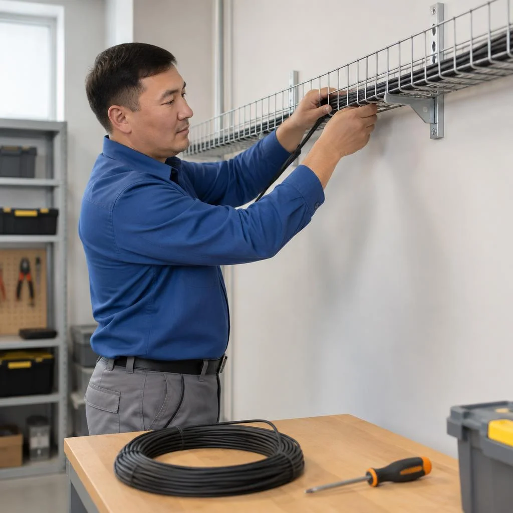
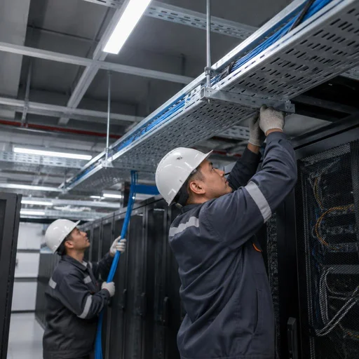
We install wire mesh trays for low-voltage and structured cabling systems, and ladder trays for heavy main lines with large support spacing and high load. A wire mesh system with a diameter of 4-6 mm is suitable for twisted pair, fiber optics, and signal lines in offices and server rooms: it bends on site without a bending machine, is cut with tin snips, and costs less than boxes at purchase. A ladder tray with a side height of 50-100 mm and a load-bearing capacity of up to 200 kg per meter is used on main lines between workshops and on long spans, where the fastening spacing reaches 3-4 meters. A wire mesh tray is easier to cut and bend on site, but requires more fastening points — its support spacing is smaller than that of a ladder tray.
Stainless steel and non-perforated tray: aggressive environment and closed routes
We install stainless steel trays in aggressive environments and outdoors, and non-perforated ones where cable protection from dust and moisture is needed. Stainless steel grades AISI 304 and 316 are used in food production, washrooms, outdoor sections, and facilities with reagent vapors; a non-perforated box with a cover along its entire length is used on lines in dusty workshops, in bulk material warehouses, and in rooms with condensation. Eco-Service treats trays against corrosion taking into account the climate of Bishkek: continental temperature swings from −25 °C in winter to +40 °C in summer accelerate the destruction of the zinc coating on open sections. Stainless steel is more expensive to install, but in local conditions it pays off: ordinary uncoated steel corrodes within 3-5 seasons on open sections.
Comparison of tray types by facility and load
| Tray type | Where it is used | Installation feature |
|---|---|---|
| Metal | Industrial facilities, power routes | Requires grounding |
| Perforated | Commercial buildings, cable ventilation | Fastening with ties through perforation |
| Wire mesh | Low-voltage, structured cabling, offices | Small support spacing |
| Ladder | Heavy main lines, large spans | Increased fastening spacing |
| Stainless steel | Outdoors, aggressive environments | Special fasteners |
| Non-perforated | Closed routes, dust protection | Cover along the entire length |
The choice of tray type is determined by the environment, the type of cable, and the load on the route, and not only by the price per meter. At mixed facilities, two types are often combined: a ladder tray on the main line and a wire mesh tray on the branches to the equipment.
Route marking and load calculation: where cable tray installation begins
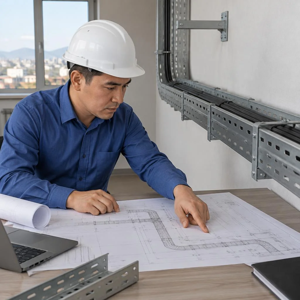
Before the first bracket comes the engineering part — marking, load calculation and the mounting scheme. These three documents determine whether the route will withstand the weight of the cable and whether the facility will pass acceptance without rework.
Route marking on site
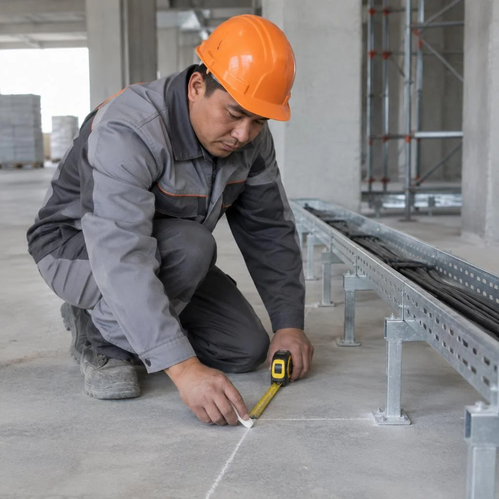
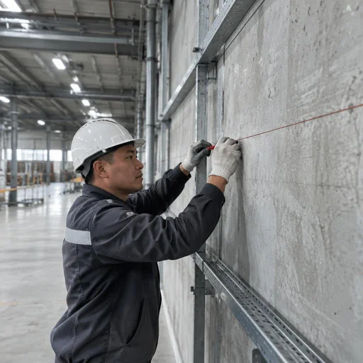
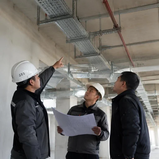
We perform marking based on the actual site — taking into account load-bearing walls, ceiling utilities and cable entry points. We start by walking through the rooms: we mark on the plan the intersections with ventilation ducts, heating pipes and cable channels that are already installed. Along the route we record in advance the locations of horizontal turns and vertical turns — at each of them up to 15 cm of usable height under the ceiling is lost, and we account for these losses before purchasing the tray. At industrial facilities in Bishkek, where ceilings are 4-6 meters, marking takes from half a day. Marking is always carried out from the entry point, not from the beginning of the wall: this way you avoid tray offcuts and unnecessary turns along the route.
Load calculation for the cable tray for a specific facility
Eco-Service calculates the load on the cable tray based on the total weight of the cable, the support spacing and the fill margin — usually no more than 60% of the tray cross-section. For a power route we take the weight of copper or aluminum per linear meter, multiply by the number of runs and add the weight of the tray itself with the cover. We select the fastening spacing so that the deflection between supports does not exceed 1/200 of the span length: for a wire mesh tray 200 mm wide this is usually 1.5-2 meters, for a ladder tray for heavy cables — 2-3 meters. We calculate the tray fill by the cross-sectional area of all cables, taking into account their diameters. The fill margin is needed not "for the future" but for the thermal regime: a densely packed tray heats up more and reduces the permissible cable current.
Tray mounting scheme and route coordination with the client
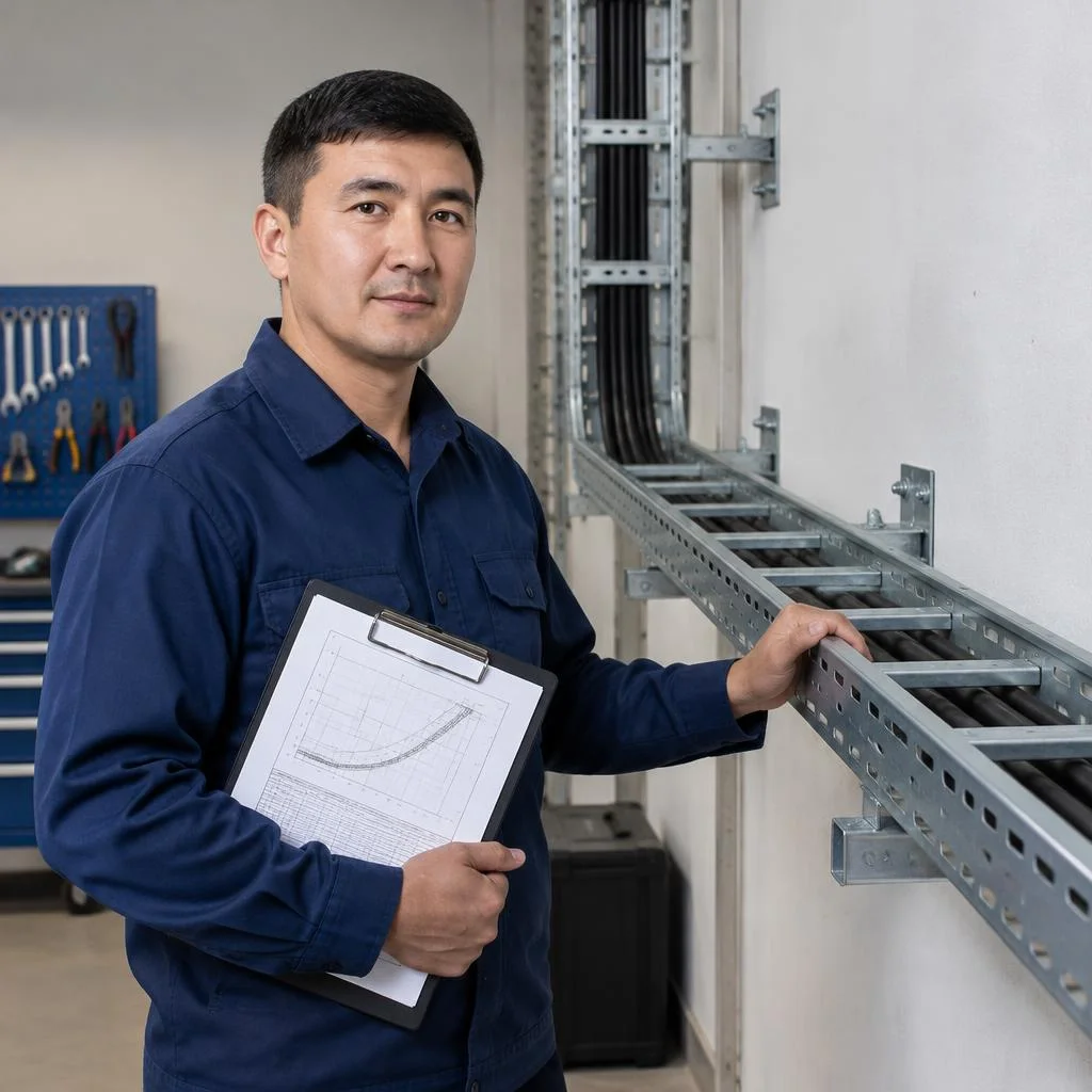
We draw up a tray mounting scheme indicating the bracket spacing, anchor types and turn assemblies, then coordinate the route with the client before installation begins. In the scheme we detail every assembly: where a ceiling suspension on a stud runs, where a wall bracket goes, where a reinforced cantilever is needed for a heavy cable run. For concrete and brick we select anchors for the specific pull-out load, for drywall partitions — embedded supports or through fasteners. Coordination is done on a sheet with elevation marks and reference to the building axes — this same sheet then goes to the installers as working documentation. In requests, clients often write briefly: a full cycle from marking to handover of the facility is needed — and from such a request we immediately understand the scope of work. A coordinated scheme saves time on site: disputed assemblies (intersection with ventilation, passage through a wall) are resolved on paper, not during the process. Cable tray installation on site without a coordinated scheme almost always runs into rework at the acceptance stage.
Cable tray installation: fastening, assemblies and turns
Tray installation is not just the tray itself, but also the supporting system: brackets, hangers, crossbars and fittings from which an entire route is assembled. Let's look at how the tray is fastened to the wall and ceiling, where reinforced cantilevers are needed, and which assemblies are installed at turns.
Fastening the tray to the wall and ceiling: brackets, hangers, anchors
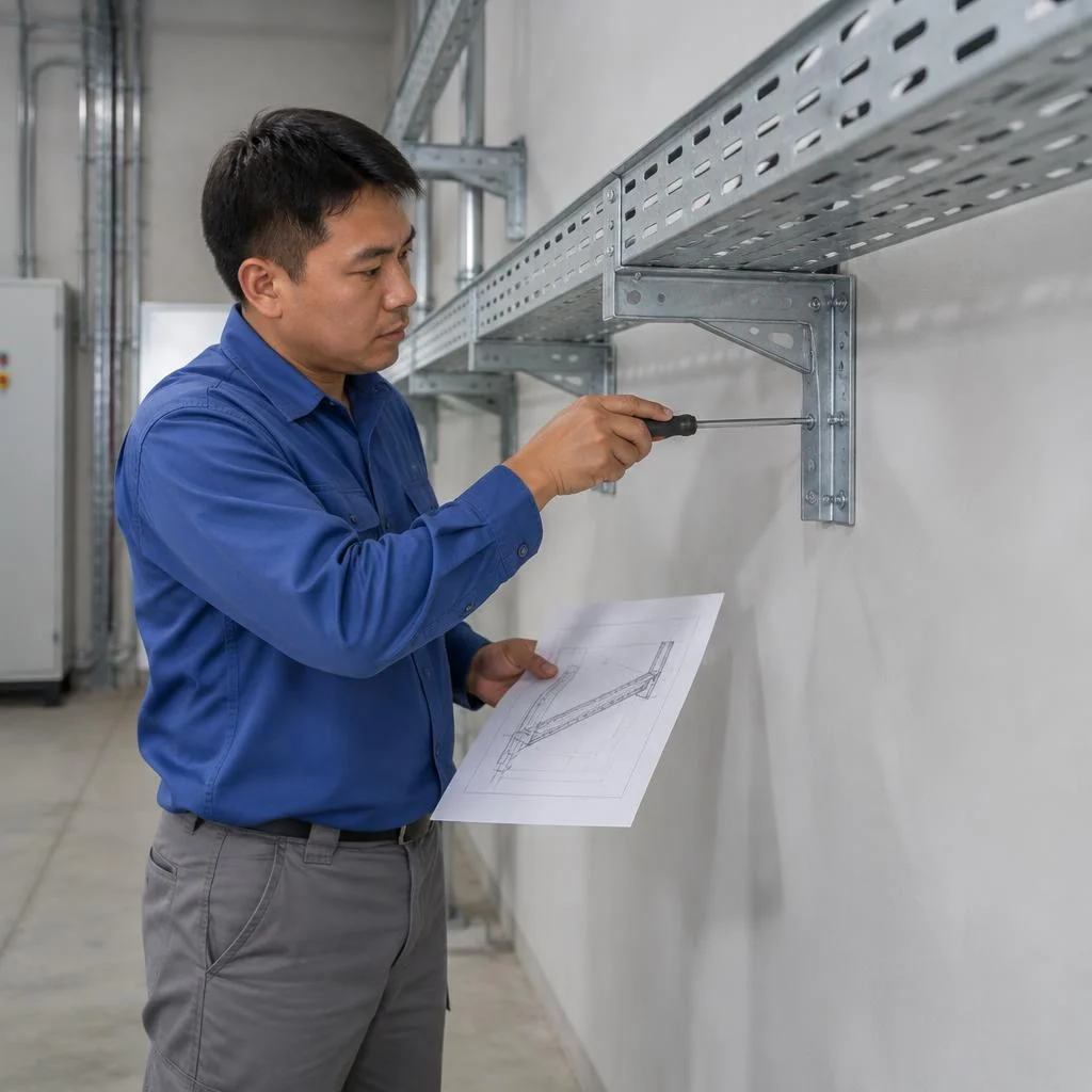
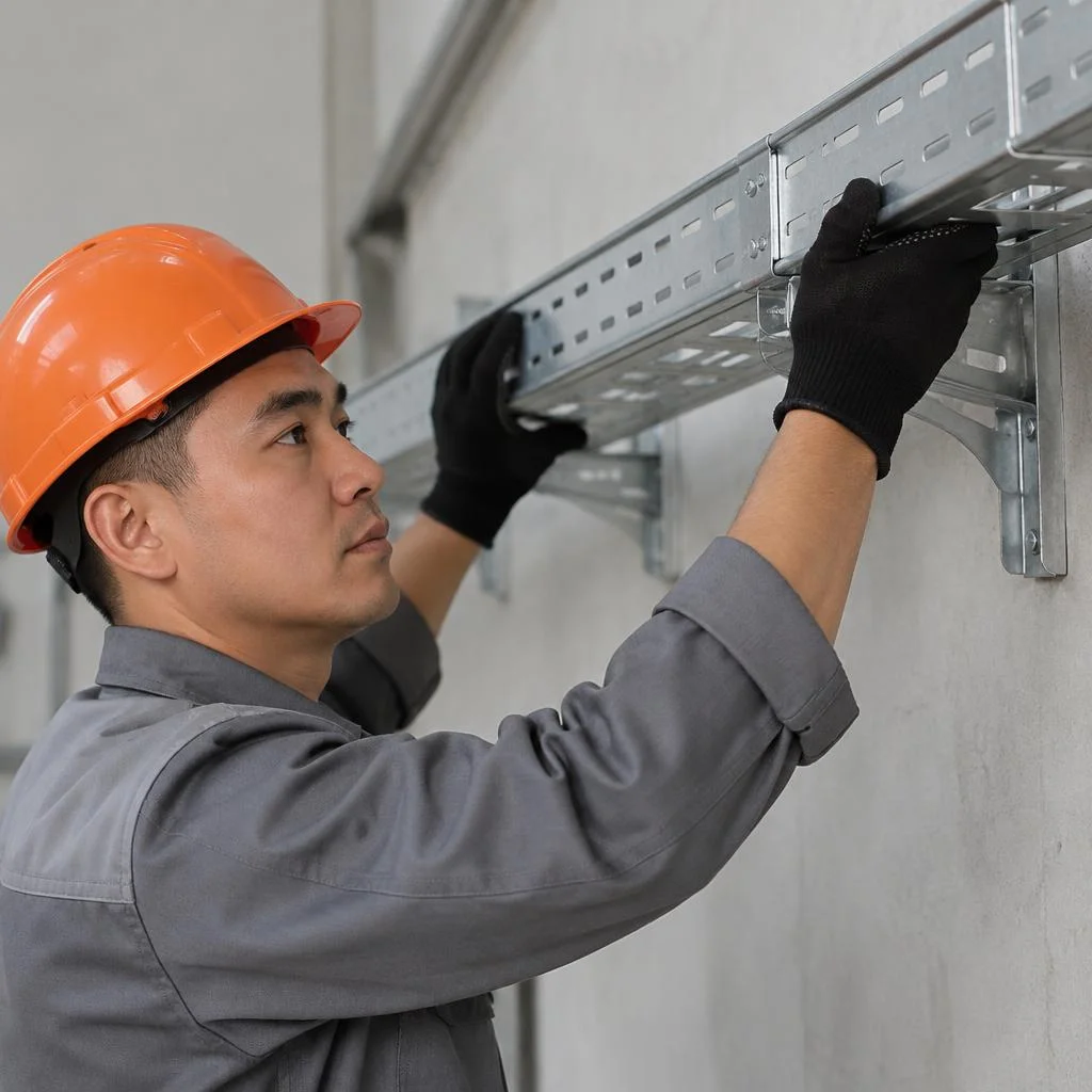
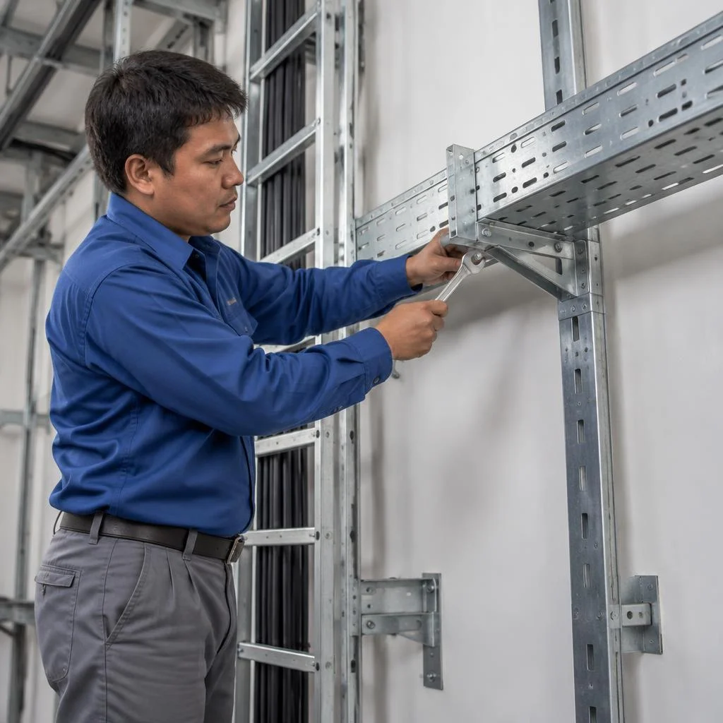
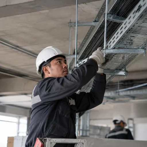
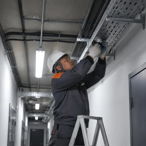
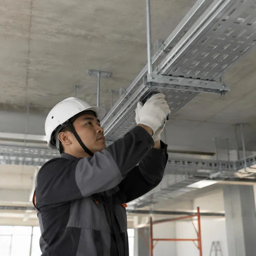
Eco-Service fastens trays to the wall on brackets, to the ceiling — on hangers; we fix the supporting elements with anchors taking into account the base material. On brick walls with old masonry and hollow concrete, a wedge anchor holds poorly, so we switch to chemical or through fastening through the slab. We calculate the support spacing based on the weight of the filled route: an empty tray weighs little, but with power cable the load on the fastening point increases many times over. At sites in Bishkek with old concrete and hollow brick, the anchor is selected by trial tightening before serial installation, otherwise the bracket is torn out under load within a month. Installation of the route begins precisely with checking the base — this stage determines which fastener will withstand the weight of the filled route. The cable tray installation price depends on the type of support and fastening, so the trial assembly is agreed upon before work starts.
Crossbars and reinforced cantilevers for the tray
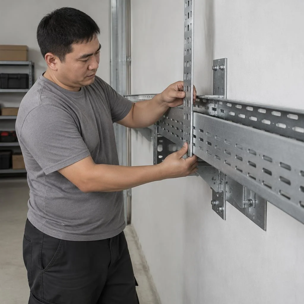
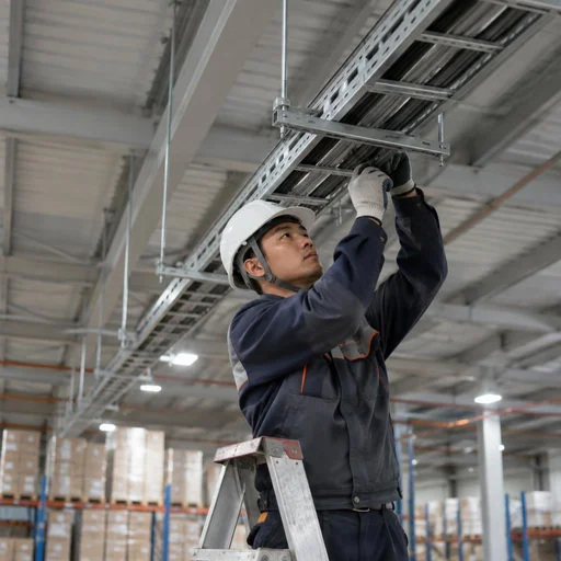
We install crossbars and reinforced cantilevers on wide trays and in places with increased load — for example, on main lines with large-cross-section power cable. The crossbar works as a load-bearing cross member: it distributes the weight between two fastening points and prevents the tray from wobbling with a shelf of 300 mm and above. A reinforced cantilever is needed where the support spacing is forced to be increased — bypassing ventilation, beams, process equipment. A standard cantilever with a span of more than a meter produces noticeable deflection, and the tray sags between the points. A reinforced cantilever does not replace calculation: if the support spacing is excessive, even a heavy-duty part results in tray deflection between the fastening points.
Turns, tees, crosses and width adapters
We install horizontal and vertical turns, tees, crosses and width adapters — they allow bypassing obstacles and routing the line without sharp cable bends. A horizontal turn changes direction in the ceiling plane, a vertical one transfers the route between levels, for example from a height of 3.5 m to 2.7 m when descending to the panel. A cable tee provides a branch to equipment, a tray cross assembles the intersection of two main lines, and a width adapter joins sections of different shelf widths — say, 200 and 400 mm. The cable bend radius is more important than the tray geometry: if a fitting forces the cable to bend more sharply than the norm, the assembly is redone rather than "forced". That is why fittings are selected for the cable brand already at the schematic stage, and not as found on site.
Route assemblies and their purpose
| Element | Purpose | Where installed |
|---|---|---|
| Wall bracket | Fastening the tray to the wall | Vertical sections |
| Ceiling hanger | Fastening to the ceiling | Horizontal main lines |
| Crossbar for the tray | Load-bearing cross member | Wide trays |
| Reinforced cantilever | Reinforced fastening | Increased load |
| Horizontal turn | Change of direction in the plane | Bypassing walls and columns |
| Vertical turn | Transition between levels | Descents and ascents |
| Cable tee | Branching of the route | Branches to equipment |
| Tray cross | Intersection of routes | Main line assemblies |
| Width adapter | Joint of trays of different widths | Transition between sections |
Fittings are ordered together with the tray: adding them during installation lengthens the timeline and results in a mismatch in coating.
Laying cable in a tray: fill ratio, bends and grounding
After the support system is installed, cable laying begins. Three parameters are decided here: tray fill ratio, minimum bend radii and mandatory grounding of the metal route.
Laying cable in a tray: fill ratio and bend radius
We lay cable in the tray with a fill ratio of no more than 60% and compliance with the minimum bend radius for each type of cable. For power lines with a cross-section up to 16 mm², we set the radius at no less than ten cable diameters; for control and low-voltage cables, no less than six. In ladder and perforated systems, we secure the cable with ties every 300-400 mm so that during pulling it does not slide down to the lowest point of the span. Installation on sites with a dense route requires a length allowance at turns: a taut cable, under thermal expansion, pushes out the fasteners and deforms the insulation. On bundles of five or more lines, we leave an air gap between rows — it dissipates heat and simplifies subsequent replacement of an individual core.
Grounding of metal trays
We perform grounding of metal trays — this is a mandatory requirement for power routes; without it, the site will not pass acceptance. We connect each section with a copper jumper with a cross-section of 6 mm² using an M6 bolt, and we connect the route itself to the building's grounding loop at least every 20 meters and at both ends of the line. Not only the tray is grounded, but also every joint: if sections are connected without a jumper, the continuity of the route is lost at the coating break. Before closing the route, we test it with an ohmmeter — the transition resistance between the farthest points must not exceed 0.05 Ohm.
Anti-corrosion treatment and route slope
We treat trays against corrosion taking into account the climate of Bishkek and set a slope on sections where moisture accumulation is possible. In unheated warehouses and on open trestles, we use stainless steel trays or hot-dip galvanized ones with an additional layer of zinc-filled primer on cut edges and drilled spots. We set the slope at 2-3 mm per linear meter toward the drainage point. The slope is needed not only outdoors: in unheated premises, condensate flows along the tray to the lowest point, and without a slope, moisture stands in the tray. This approach to route installation extends the service life without repainting for years to come.
Standards and typical errors when laying cables in trays
Some defects on the route are visible immediately after installation, while others only appear during acceptance or after months of operation. We break down what exactly is standardized and where installers most often slip up.
What PUE and GOST standardize when installing trays
PUE and GOST set the fastening spacing, permissible tray fill, cable bend radii, and requirements for grounding metal routes. The Electrical Installation Code ties the support spacing to the design load per linear meter, while the industry GOSTs for trays and fasteners tie it to metal thickness, the load-bearing capacity of the bracket, and the anchor assembly. The permissible fill by cross-section is kept within 35-50% for power lines and up to 50-60% for low-voltage lines, and the minimum bend radius of a cable with a copper conductor is 6-10 outer diameters depending on the insulation type. Grounding of the metal route is standardized separately: the tray must have a continuous circuit with resistance corresponding to the equipotential bonding system. The standards give a range, not a ready-made number: the fastening spacing is selected based on the load and tray type, so a typical diagram from the internet often does not suit the project — calculate the deflection for the specific route.
Typical errors when installing cable trays
- Excessive fastening spacing: the tray sags under the weight of the cable between supports, and the defect worsens over time.
- Dense filling: the cable heats up, the permissible current decreases, and the insulation ages faster than the design life.
- No grounding: the metal route fails acceptance and does not perform its protective function.
- Sharp bends: the cable bend radius is violated at turns, the conductor deforms and loses conductivity.
- No slack at turns: the cable is taut and presses on the fasteners, and the assemblies loosen under thermal movement.
What errors cost you when handing over a project
Laying cables in trays does not tolerate approximate solutions: excessive fastening spacing is not immediately visible — the tray stands straight, but under load it sags between supports, and the defect shows up after months of operation. During acceptance, the inspector checks the continuity of the grounding circuit, the actual fill by cross-section, compliance with the bend radius at turns, and the condition of the fasteners under load. Laying a route with a margin of load-bearing capacity and correct grounding costs less than redoing it after comments: dismantling, replacing fasteners, and re-acceptance stretch the project timeline by weeks. In our practice on commercial projects in Bishkek, it is most often the assemblies at turns that have to be redone — there, saving on cross-arms and brackets produces maximum deflection, and you have to fix an already installed route while adjacent lines are energized.
Warranty, acceptance and route maintenance
After installation, not only is there a finished route, but also the contractor's obligations: acceptance, warranty period and maintenance. Let's break down exactly what is recorded at handover and how post-installation service is structured.
Acceptance of the facility and handover certificate
We hand over the facility by certificate: the customer receives a route diagram, a grounding resistance measurement report and confirmation that the installed assemblies comply with the design. The package includes an as-built drawing of tray fastening with reference to the building axes, a list of the brackets and hangers used, as well as certificates for concealed works — anchor fastening and the grounding loop. At industrial facilities in Bishkek, acceptance is carried out by the customer's technical supervision, and we pass it without remarks, because route assemblies are checked against a checklist at every stage, not at the end. The handover certificate records not only the fact of the works, but also the service points — it makes it easier to find a specific assembly during subsequent repair or expansion of the route.
2-year warranty and a service center in the capital
Eco-Service provides a 2-year warranty on cable tray installation, and the service center operates in Bishkek with in-person acceptance of requests. The warranty period covers fasteners, bend assemblies, traverses and grounding connections; when contacted, a technician travels to the site, checks the condition of the route against the handover certificate and eliminates the defect. Requests are accepted year-round, and the response time depends on workload, but emergency cases — tray sagging, a separated joint, a grounding fault — are taken into work first. If a client compares contractors by the parameter cable tray installation price, it is worth looking not only at the estimate: the warranty covers not only fasteners, but also route assemblies, and if a bend or joint came apart through our fault, the visit and rework are at the service's expense.
Maintenance of cable routes after installation
We maintain cable routes after installation: we check fasteners, grounding and the condition of the coating according to the schedule. A planned inspection includes tightening bolted connections on brackets and cantilevers, measuring the resistance of the grounding loop, visual monitoring of the anti-corrosion layer and checking tray fill — whether cable sagging has appeared at bends. At warehouses and production sites in the capital, inspection is carried out once every six months; in office centers, an annual visit is sufficient. A planned inspection is cheaper than emergency repair: a loosened bracket is found in minutes, while a fallen tray with cable stops the facility's operation.
Conclusion
Cable tray installation rests on three supports: the right type selected for the environment, accurate calculation before installation and careful laying with grounding. Below are brief conclusions worth keeping at hand when planning a route.
Key conclusions
- Tray type — for the environment and load: metal, perforated, wire mesh, ladder or stainless steel are selected by cable type, humidity and route weight, not by price per meter.
- Design before installation: marking, load calculation and the fastening scheme determine whether the facility will pass acceptance without rework.
- Laying according to standards: tray fill no more than 60%, cable bend radius — according to its datasheet, grounding of metal trays is mandatory along the entire route.
- Fittings in advance: bends, tees, crosses and width adapters are included in the specification right away — adding them along the way extends deadlines by days.
- Acceptance and maintenance: the handover certificate records the scope of works, and planned inspection of fastenings and the anti-corrosion coating extends the service life of the route.