









What a manifold is and what tasks it solves in the system
A manifold is a distribution unit that evenly supplies the heat carrier or water through the loops. Without it, the system operates unevenly: some branches overheat while others remain cold.
Design of a distribution manifold: what the unit consists of
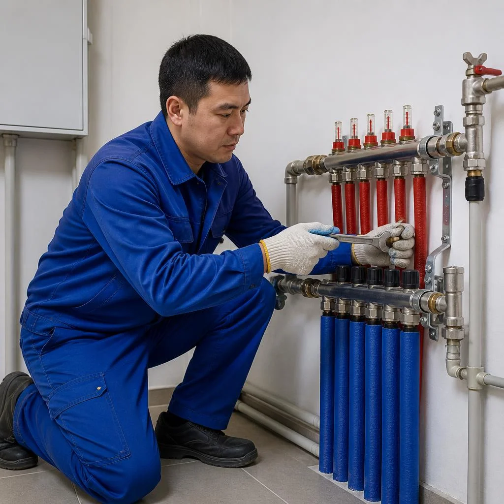
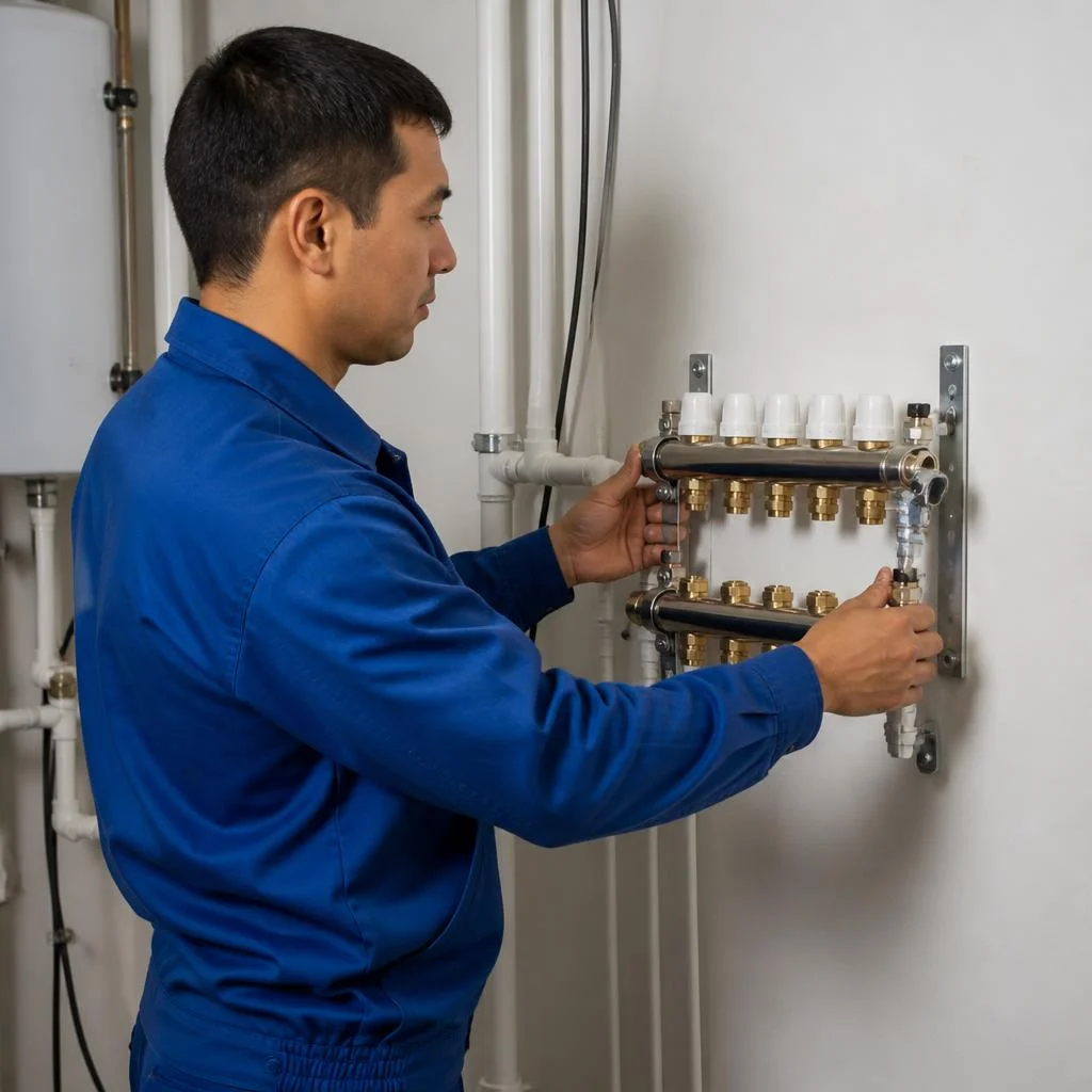
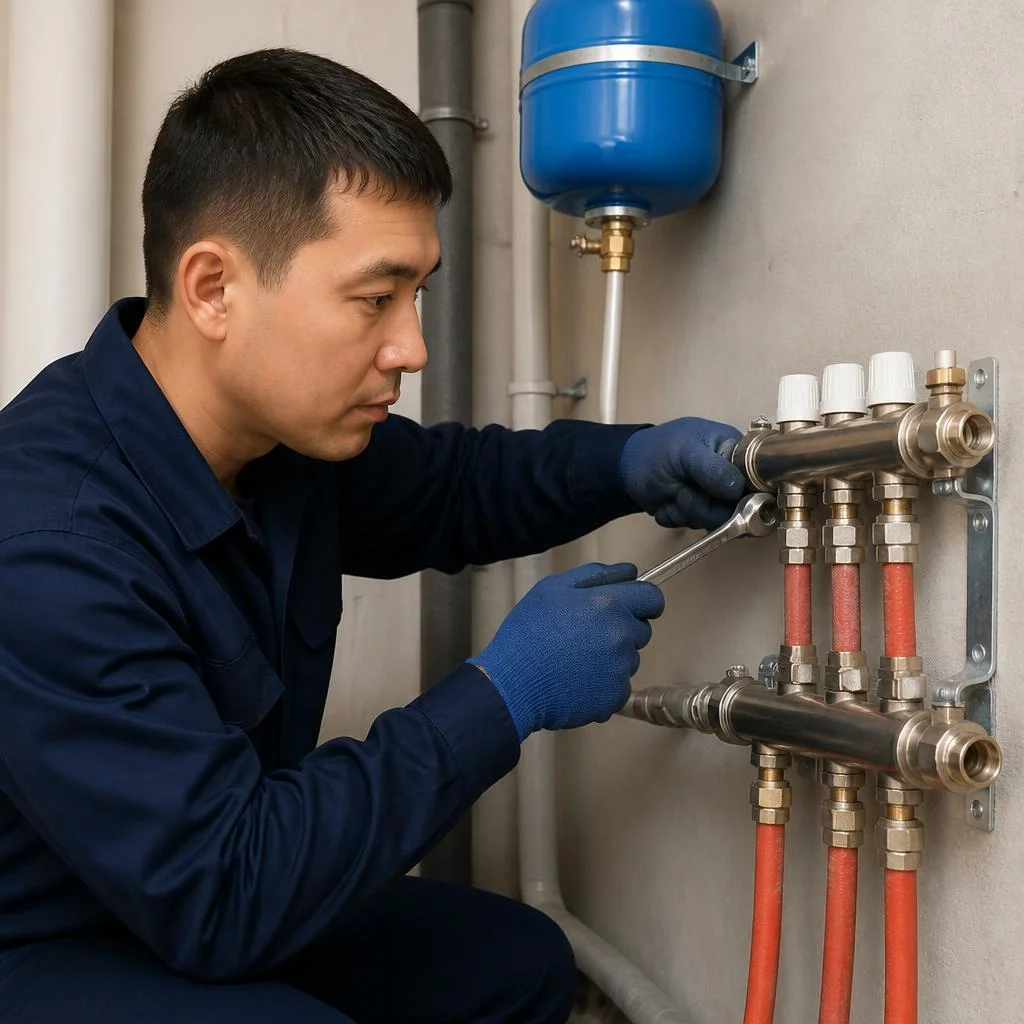
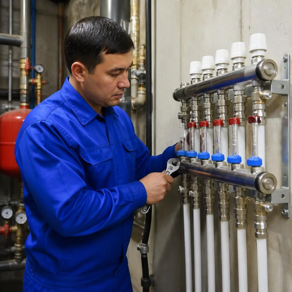
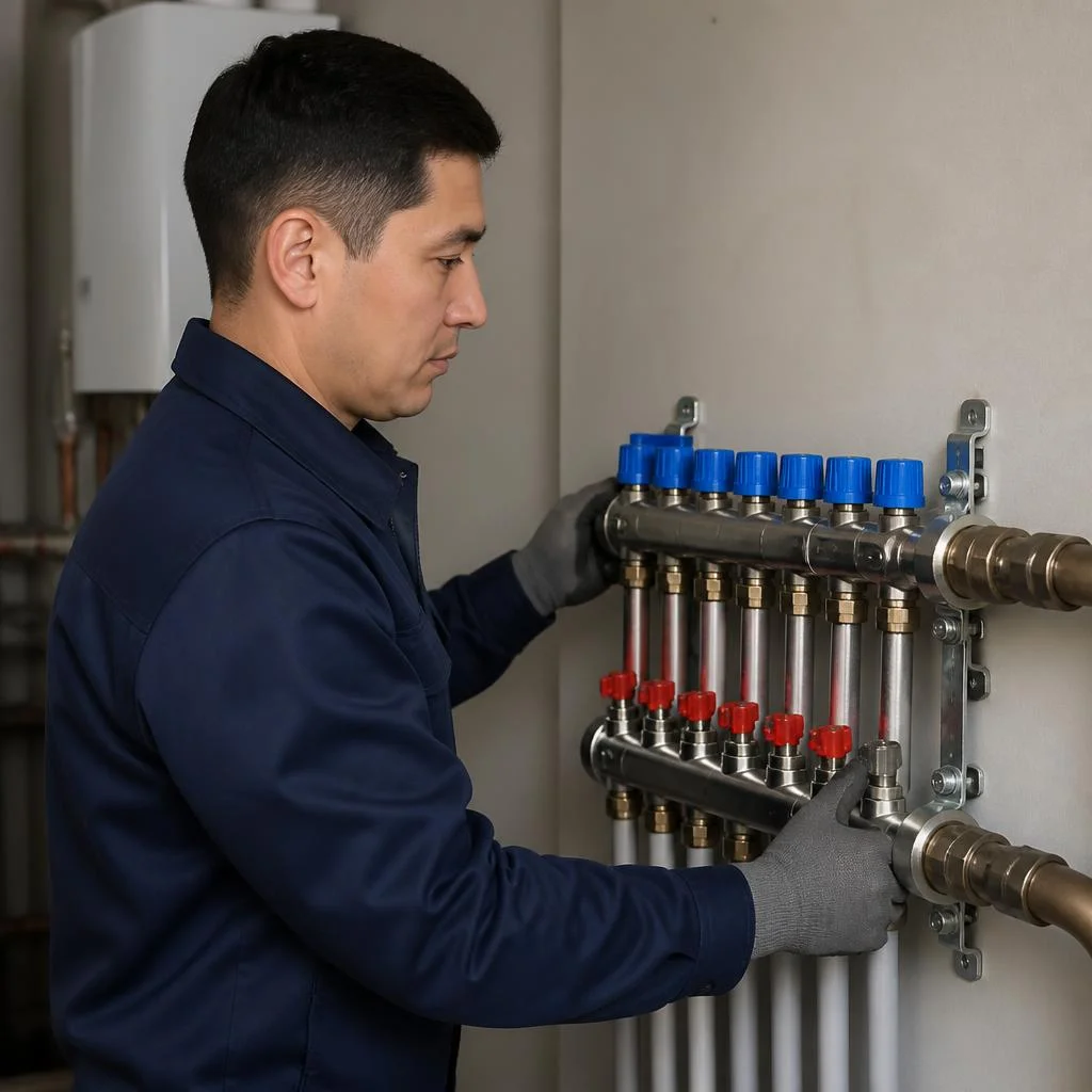
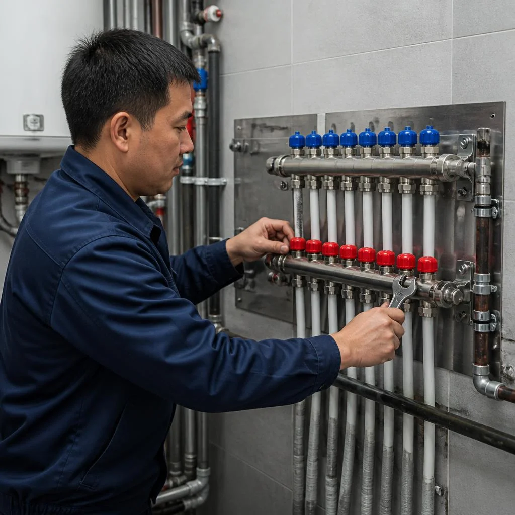
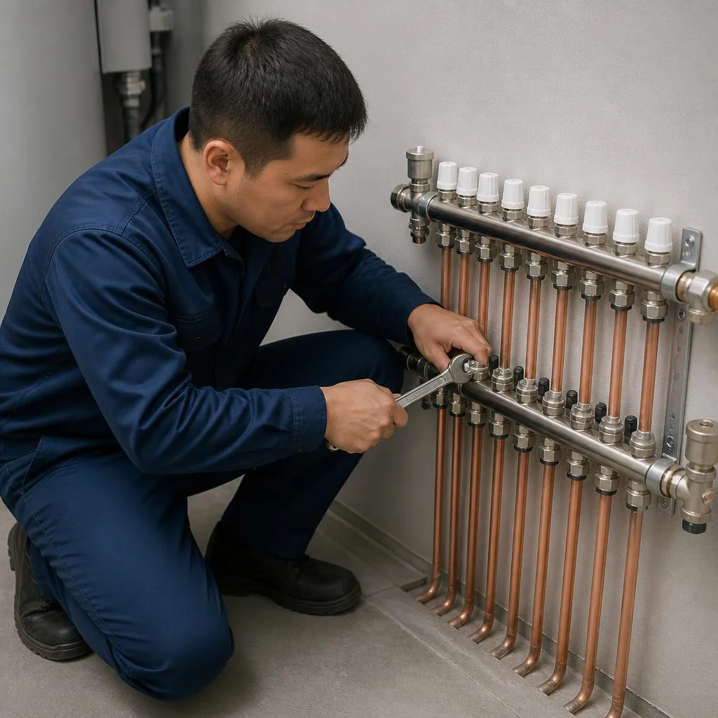
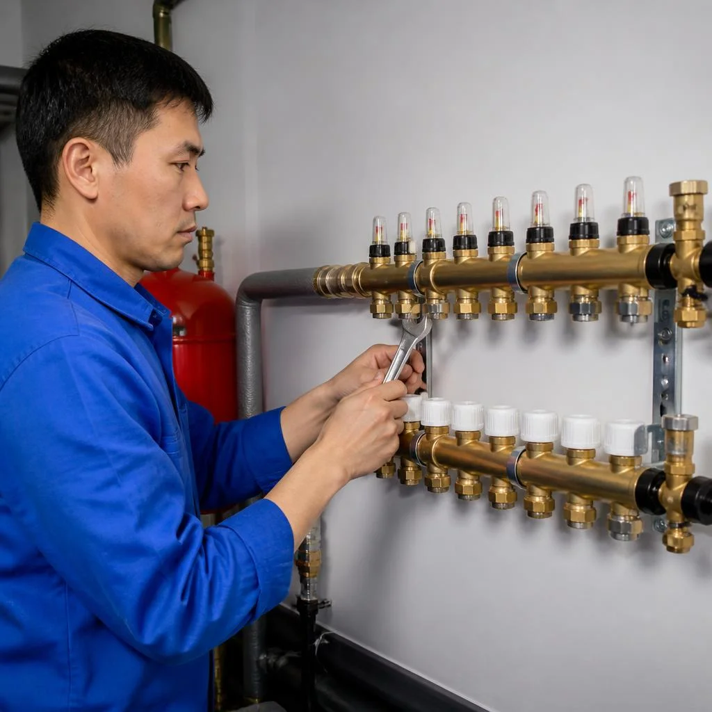
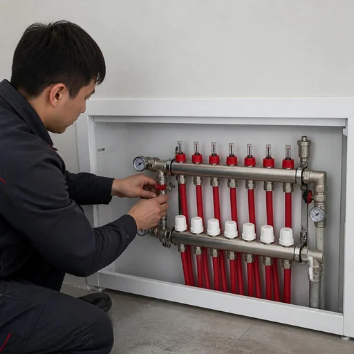
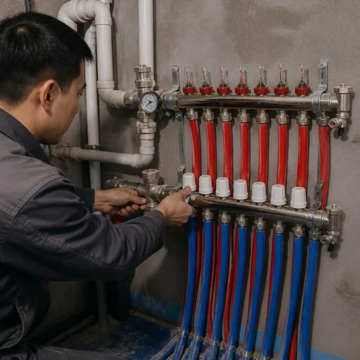
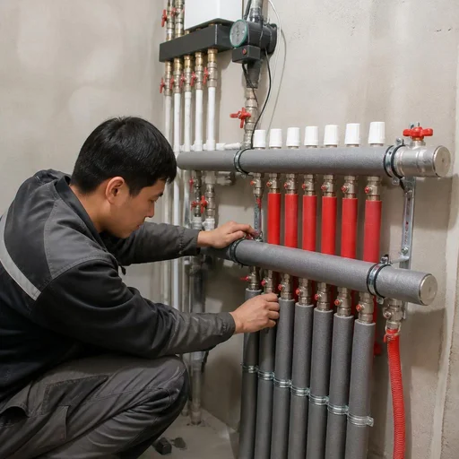
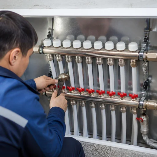
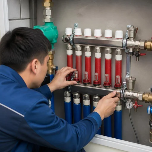
A distribution manifold is a collector with supply and return bars, to which the system loops are connected via euroconus fittings and nipples. The body is assembled from brass or stainless steel with a nominal diameter of DN25 or DN32 — for distribution of up to 12 loops per floor. Flow meters are installed on the supply bar, and balancing valves on the return bar; an automatic air vent and a drain valve are mounted on top. The nipples are selected to match the pipe diameter: 16 or 20 mm for multilayer composite and PE-RT. The more loops there are, the more important balancing becomes — without it, the distant branches receive insufficient heat carrier, and the system operates unevenly.
How a heating manifold differs from an underfloor heating manifold and a water supply manifold
- Heating manifold: works with a high-temperature heat carrier of 70-90 °C and radiators, and is equipped with valves and thermostatic heads for room-by-room control.
- Underfloor heating manifold: designed for a low-temperature loop of 35-45 °C, and necessarily includes a pump mixing unit with a thermostatic head for blending the return flow.
- Water supply manifold: distributes cold and hot water at a pressure of up to 10 bar; instead of flow meters, shut-off valves are installed for each outlet point.
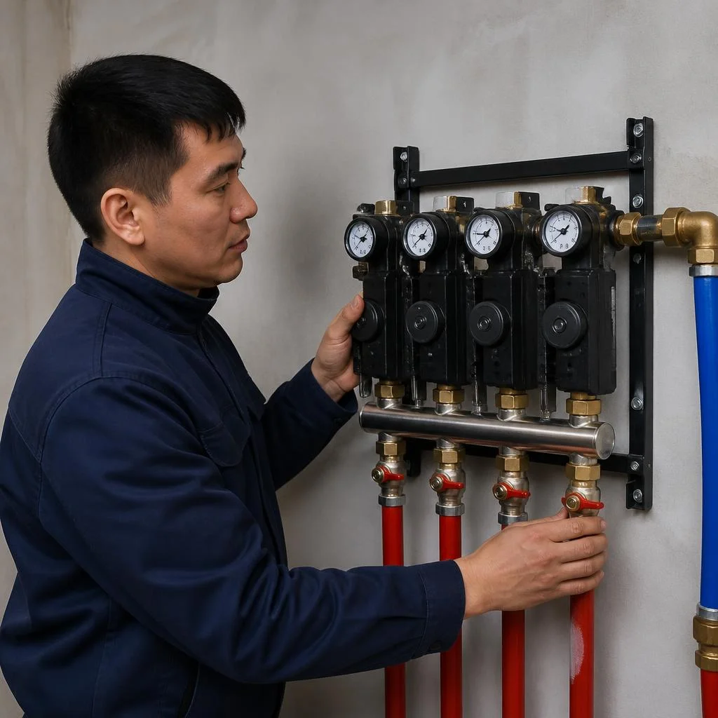
- Pump mixing unit: blends the underfloor heating return flow into the supply, keeping the temperature in the loops at a level safe for the screed.
When you can't do without a manifold: scenarios for an apartment and a house
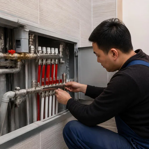
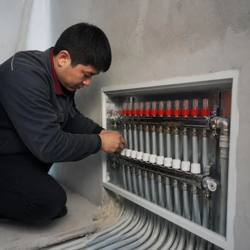
A manifold is needed when the system has more than two loops: radiators in different rooms, several underfloor heating loops, or water distribution to several points. In a two-storey house of 150-200 m², there are usually 8-12 underfloor heating loops — they are brought together onto a single manifold in the boiler room or a separate manifold cabinet. In an apartment with a riser, the manifold unit is installed in a cabinet near the entrance — this simplifies maintenance and does not spoil the interior. Concealed installation in a wall chase without an inspection hatch is unacceptable: if air enters the system or a flow meter needs replacing, the wall will have to be opened up. Clients often phrase the request as heating manifold installation — in essence, this is assembling the manifold unit, connecting the loops and balancing the flow meters on site. At the design stage, allow for a cabinet at least 110 mm deep and a 220 V power supply if automation with actuators is planned.
Assembling a heating manifold: stages and what the work includes
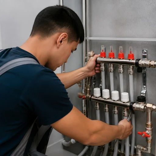
Installing a heating manifold includes marking out, mounting the manifold, assembling the unit, piping it up and pressure testing — each stage affects the system's tightness. Below we break down the sequence of work and the points where mistakes most often occur.
Preparation and marking out: where manifold installation begins
We start by marking out the location for the manifold cabinet and checking the tie-in points to the riser or boiler. On Bishkek sites this is most often a niche in the bathroom, hallway or the boiler room of a private house — the length of the supply lines and the number of bends depend on it. We carry out marking along the actual axes of the riser: shifting the manifold 150-200 mm from the design point forces you to extend the supply line and add fittings, and every joint is a potential leak. When installing manifolds in Bishkek, we begin by checking the depth of the cabinet for flow meters and thermostatic heads — at the marking stage this determines whether the valves will fit without rework. We allow for slope and service access in advance: if the cabinet sits flush against the wall, the balancing valves cannot be adjusted afterwards.
Mounting the manifold and assembling the unit
- Brackets: two or three brackets in the cabinet, we set the horizontal by level — a tilt causes air pockets in the upper outlets.
- Shut-off valves: ball valves on the supply and return manifolds isolate the unit from the system without draining the entire circuit.
- Air vents: automatic valves at the top point of the manifold, manual ones at the ends, if the manifold model provides for this.
- Drain valve: at the bottom point of the return manifold — through it we drain the heat carrier during repairs or flushing.
- Assembling the unit: we seal threaded connections with flax and paste or anaerobic sealant, and tighten with a torque wrench.
Piping the manifold and connecting it to the boiler
We pipe the manifold and connect it to the gas boiler through a circulation pump. For apartment systems in Bishkek we most often use reinforced polypropylene or cross-linked polyethylene PEX-a with press fittings, for private houses — steel or copper for soldering. We install the pump on the return line before the boiler: the heat carrier temperature is lower there, so the service life of the bearings and seals is longer. If the manifold serves a radiator branch, we add a bypass with a three-way valve between the supply and return — this protects the boiler from cold return water. When piping, it is important to maintain the pipe diameter for DN25 or DN32 — narrowing on the supply reduces flow rate and leads to uneven heating.
Pressure testing and system start-up
We pressure test the unit under pressure and start up the system, checking the tightness of every connection. We take the test pressure one and a half times higher than the working pressure, hold the unit under it for at least 30 minutes and inspect all threaded and press joints. For radiator systems in Bishkek apartment blocks the working pressure is usually 6-8 bar, for private houses with a gas boiler — 1.5-2 bar. After pressure testing we fill the circuits, expel air through the air vents and start the circulation pump at minimum speed, gradually raising it to working. Pressure testing is done before pouring the screed — if a leak is found afterwards, the floor will have to be opened up.
Installation of a water supply manifold: features and differences from heating
A water supply manifold distributes cold and hot water to the draw-off points — its installation differs from a heating unit in working pressure, materials and the set of fittings. Let's look at the design, the key differences and the components of a water manifold.
How a water supply manifold is designed and where it is installed
We install a water supply manifold in a manifold cabinet or a plumbing niche, connecting it to the cold and hot water riser and running separate lines to each draw-off point — the kitchen, bathrooms, washing machine, water heater. The typical scheme is two manifolds (cold water and hot water) with 3-6 outlets, mounted on brackets with spacing to match the diameter of the supply lines. Installing a manifold saves up to 30% of repair time: one branch is shut off, not the entire riser. In Bishkek, in 1980s panel buildings, risers are often replaced with polypropylene up to the manifold unit — in that case the manifold is installed after the meter so as not to dismantle the existing distribution. In search, clients type "water supply manifold installation price" — and land on this page. For water supply, brass or stainless steel manifolds are used — polypropylene ones hold pressure worse during water hammer, which occurs in the city network during shutdowns and when the riser is being filled.
How water supply manifold installation differs from heating manifold installation
| Parameter | Water supply manifold | Heating manifold |
|---|---|---|
| Working pressure | 3-10 bar | 1.5-2.5 bar |
| Medium temperature | up to 75 °C (hot water) | up to 90 °C |
| Main fittings | meters, pressure reducers | balancing valves |
| Flow regulation | not required | thermostatic heads, flow meters |
| Air vent | on the hot water manifold | on both manifolds |
| Body material | brass, stainless steel | brass, stainless steel, steel |
In water supply there is no balancing or thermostatic heads, but there are meters and pressure reducers; in heating there are balancing valves and air vents. A pressure reducer at the inlet to the water supply manifold protects household appliances from surges in the city network: during a water hammer of up to 10 bar, the membrane of a washing machine or boiler fails in a single cycle.
Materials and fittings for a water manifold
- Brass manifold: nickel-plated body with 3-6 outlets, withstands working pressure up to 10 bar, threaded connections 1/2" or 3/4".
- Stainless steel manifold: seamless pipe with welded nipples, used at pressures above 10 bar and in systems with aggressive water.
- Shut-off valves: ball valves on each branch, allow shutting off an individual point without stopping the entire system.
- Drain valve: at the lowest point of the manifold, needed for seasonal maintenance and draining the system without dismantling the unit.
- Air vents: automatic valves on the hot water manifold, release the air lock after the summer hot water shutdown.
Installation of a underfloor heating manifold: circuits, balancing and adjustment
Installing a underfloor heating manifold requires a pump-and-mixing unit, balancing of the circuits and precise calculation of the number of loops for the room area. Below we break down each stage with the parameters that we use on sites.
Calculating the number of circuits for the room area
We calculate the number of circuits by area: one underfloor heating loop covers up to 15–20 m² with a laying pitch of 15–20 cm. Clients often search for underfloor heating manifold installation price — and land on this calculation, because the number of manifold outlets directly determines the estimate. In new buildings in Bishkek (residential complexes "Ala-Too", "Baitik", the blocks along Jibek-Jolu street) we cover a 4–6 m² bathroom with one loop, a 28–32 m² kitchen-living room with two, a 16 m² bedroom with one at a 15 cm pitch. For each square meter at a 20 cm pitch, about 5–6 linear meters of pipe are used, at a 15 cm pitch — up to 7. In search, the query Manifold installation is entered both by those planning wiring from scratch and by those adding loops to an existing manifold. If a loop is longer than 100 meters, the pump will not push the circuit through — it is better to split the room into two loops and connect them to different manifold outlets.
Connecting underfloor heating circuits to the manifold
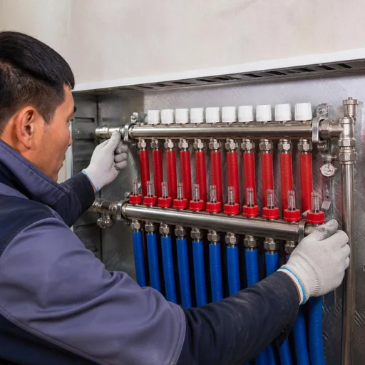
We connect underfloor heating circuits to the manifold via euroconus fittings, install flow meters and balancing valves on each outlet. We work with PE-RT and PEX-a pipe with diameters of 16 and 20 mm: we install the euroconus for 16 mm on loops up to 80 meters, for 20 mm — on the long circuits of living rooms and corridors. On the supply manifold we mount flow meters with a scale of 0.5–4 l/min, on the return — balancing valves with a cap for a hex key. The connection of underfloor heating circuits is carried out by the Eco-Service crew with pressure testing of each outlet before pouring the screed. Flow meters are placed on the supply manifold — they show which circuit is not receiving enough heat carrier, and balancing can be carried out without dismantling.
Balancing and adjustment of the underfloor heating system
We balance the circuits via the flow meters and adjust the thermostatic heads so that each loop receives the required heat carrier flow rate. The guideline for residential premises is 1.5–2.5 l/min per loop with a supply and return temperature difference of 5–7 °C; for bathrooms and corridors we reduce the flow rate to 1–1.5 l/min. Eco-Service sets the balancing valves according to the flow meter readings, not "by eye": on an 8-circuit manifold, the difference between the longest and the shortest loop easily reaches 2 l/min, and without adjustment the far room remains cold. We install thermostatic heads with remote sensors in bedrooms and children's rooms — precise control is needed there. Balancing is done after the first heating of the screed — on a cold system the flow meters show incorrect values.
Pump-and-mixing unit: why it is needed
We install a pump-and-mixing unit that lowers the heat carrier temperature to 35–45 °C before supplying it to the underfloor heating circuits. The unit includes a three-way valve with a thermostatic head, a circulation pump with a wet rotor (Grundfos, Wilo, DAB — available in Bishkek), a bypass and thermometers on the supply and return. Eco-Service selects the pump-and-mixing unit for the power of the circuits: for 60–80 m² of underfloor heating, a pump with a head of 4–6 m and a flow rate of 1.5–2.5 m³/h is sufficient. We set the supply temperature to 40 °C at an outdoor temperature of −10 °C and to 45 °C at −25 °C — the thermostatic head mixes in the return itself. Without a mixing unit, the hot heat carrier from the boiler (70–80 °C) will overheat the screed and cause cracks — the unit is mandatory for water underfloor heating.
Fittings and components: what is installed on the manifold
System controllability depends on the fittings: shut-off valves, balancing valves, flow meters and thermostatic heads solve different tasks, and the set of elements is selected for a specific type of layout.
Shut-off valves and drain valve: basic piping
- Shut-off valve on the supply: shuts off the supply manifold entirely or an individual outlet — Eco-Service installs them on every circuit.
- Shut-off valve on the return: a paired element on the return manifold; without it, the unit cannot be removed for inspection.
- Drain valve: mounted at the lowest point of the manifold; the coolant is drained through it during maintenance.
- Ball mechanism: full bore without narrowing, service life — over 10,000 open and close cycles.
- Butterfly handle: convenient in cramped manifold cabinets, where a handwheel does not fit between adjacent outlets.
Balancing valves and flow meters
We install balancing valves on the return manifold and flow meters on the supply manifold — together they provide flow control for each circuit. The balancing valve closes or partially opens the passage, equalizing the hydraulics between long and short loops: in private homes in Bishkek, the difference between a 40 m circuit and a 90 m loop produces an imbalance of up to 30% without adjustment. The flow meter is a transparent tube with a 0.5–4 l/min scale; the actual flow can be seen by the float. Manifold installation at Eco-Service always goes hand in hand with setting both elements: first the valve sets the design value, then the flow meter confirms the result. The balancing valve is adjusted once during commissioning, and the flow meter shows the current flow rate — it is used to check whether the setting has drifted after seasonal maintenance.
Thermostatic heads and air vents
We install thermostatic heads for temperature control by circuit and automatic air vents for removing air. A thermostatic head with a remote sensor maintains the room temperature with an accuracy of ±1 °C and works in tandem with a valve on the supply manifold; a liquid model is suitable for radiator branches, while for underfloor heating — one with limited stem travel. An air vent with a float mechanism is installed at the highest point of the manifold and releases air in portions of 5–10 ml until a gas pocket accumulates in the chamber. Eco-Service supplements the unit with automation if the system is divided into zones with different modes. The automatic air vent releases air without manual intervention, and the system does not require regular bleeding of Mayevsky valves every week.
Comparison of fittings by purpose
| Element | Purpose | Where installed | For which system |
|---|---|---|---|
| Shut-off valve | circuit isolation | supply and return | heating, water, underfloor heating |
| Balancing valve | flow equalization | return manifold | heating, underfloor heating |
| Flow meter | flow monitoring | supply manifold | underfloor heating |
| Thermostatic head | temperature control | supply manifold | heating, underfloor heating |
| Air vent | air removal | highest point | heating, underfloor heating |
| Drain valve | system draining | lowest point | heating, water |
The set of fittings depends on the type of system — for water supply, thermostatic heads and balancing valves are not needed, while for underfloor heating they are mandatory: without balancing, circuits with different loop lengths operate unevenly, and distant zones are underheated.
Warranty, timelines and terms of Eco-Service work
This section covers what the client relies on when placing an order: warranty obligations, realistic timelines for site visits and assembly, and the difference between contacting a service center and a private technician.
2-year warranty on manifold assembly
Eco-Service provides a 2-year warranty on manifold assembly — it covers the tightness of connections, the operation of valves and fittings, and the correctness of balancing. The warranty period includes replacement of failed valves, fittings and flow meters if the cause is an assembly defect or incorrect setup. A claim is filed based on the work completion report: the technician records the condition of the unit, the pressure in the circuits and the pressure test result, so in a disputed situation there is something to confirm the initial parameters of the system. The warranty is valid provided the system has not been reworked by third-party technicians — if there is outside interference, warranty obligations are voided.
Work timelines and how a technician's visit proceeds
We travel to the site in Bishkek, assess the scope of work and assemble a manifold for 2–16 circuits within one working day. The technician's visit includes measuring the installation location, checking the supply pipes and agreeing on the layout scheme — as a result, the client receives a clear list of works and materials before assembly begins. At sites in new residential complexes on the outskirts of the capital, preparation takes less time: the supply lines are already installed, the walls are unfinished, and access to the manifold cabinet is unobstructed. If assembly is done in a new building before the screed is poured, the timelines are shorter — there is no need to dismantle the old layout and wait for the system to drain. In a finished apartment with active heating, draining the coolant and refilling the circuits is added, so we schedule the work for the morning so that by evening the system reaches operating mode. Clients often search for manifold installation price — and land on this page, because the final estimate depends on the number of circuits and the scope of piping, not on a fixed rate. We agree on the estimate after inspection — this eliminates additional charges during the process.
Why a direct supplier is more advantageous than a private technician
- Contractual liability: the service center issues a report and warranty card, while a private technician more often works on a verbal basis and without documents.
- Staff technicians: the work is carried out by specialists with a profile in heating and water supply, not generalists on contract.
- 2-year warranty: covers tightness, fittings and balancing — in case of a leak, the claim is made to the organization, rather than searching for a vanished contractor.
- Parts and fittings: manifolds, flow meters and valves are supplied for a specific scheme, without selecting "whatever was found on the market."
- Transparent estimate: the cost is calculated based on the number of circuits and the scope of piping before work starts, so the final amount does not change during the process.
Conclusion
We have gathered the main things worth keeping in mind before installing a manifold: from the number of circuits to the moment of pressure testing. Below are five conclusions that most often come up in conversation with the client.
Main conclusions
- More than two circuits: a manifold is needed when radiators, underfloor heating loops or water distribution branch into separate lines in the system.
- Underfloor heating: without a pump mixing unit and balancing via flow meters, the circuits heat unevenly — the far loops remain cold.
- Water supply: a water manifold differs from a heating one — there are no thermostatic heads here, but there is a pressure reducer and spaces for meters.
- Pressure testing: it is done before pouring the screed, otherwise a leak will have to be found by opening the floor and redoing the repair.
- Fittings: shut-off valves and air vents are needed in any system, thermostatic heads — only for heating and underfloor heating.